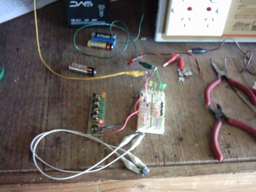
Been a long time coming, but here it is. First, a not-very-good picture of the finished article, with the prototype beside it:
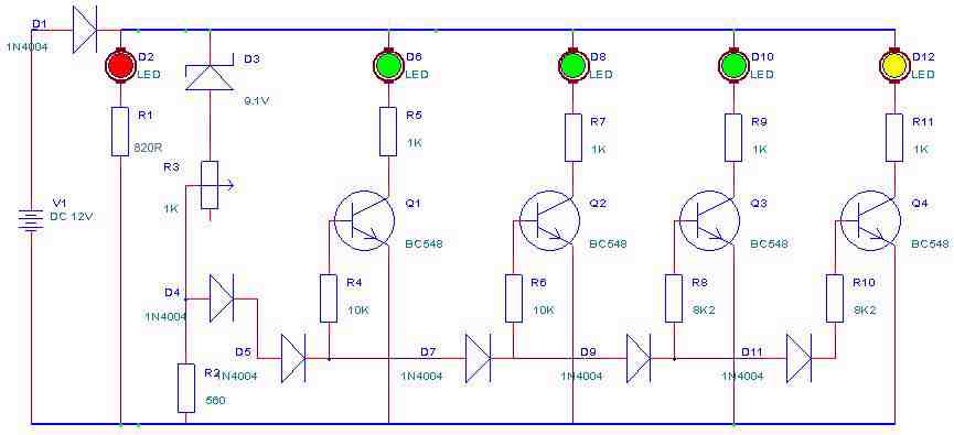
The parts list is:
- 4 x BC547 transistors;
- 6 x 1N4004 diodes;
- 1 x 560 ohm resistor;
- 1 x 820 ohm resistor (R1);
- 4 x 1K ohm resistors;
- 2 x 8.2K ohm resistors;
- 2 x 10K ohm resistors;
- 1 x 1K ohm mini horizontal trimpot;
- 1 x 9.1V Zener diode;
- 1 x 5mm red LED;
- 3 x 5mm green LED;
- 1 x 5mm yellow LED.
Here's the schematic:
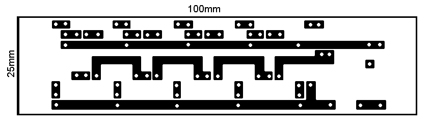
The PCB artwork:
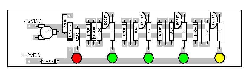
...and the component overlay:
It's pretty much self explanatory, once built you use the trimpot to set the voltage at which the green lights start to come on (I usually use about 12.1V).
Enjoy!
BTH
