Author Topic: Fish-way using low head hydro turbine  (Read 21644 times)

0 Members and 1 Guest are viewing this topic.

Ungrounded Lightning Rod

  • SuperHero Member
  • ******
  • Posts: 2865
Nice for fish. But other living things?
« Reply #33 on: May 08, 2018, 06:25:59 PM »
I like the way this concept provides a nice, low-stress, path THROUGH the turbine, for fish and other water creatures, without totally trashing the efficiency of the turbine or (as with fish ladders) setting up the fish in a long, handy, grabbing-gallery for opportunistic predators such as raccoons and bears.

But one thing troubles me about the various published designs:

How does a LAND creature that falls in get out alive?

Those things look like nasty boobytraps for small children (also adolescents and adults), pets, and wild animals.  Once jn they get spun around until they're exhausted and sink, perhaps then to get stuck underwater, with nothing to grab, nothing to climb up, no easy downstream passage with air, and so on.  There is no guard, no cover, etc. to keep them from falling in, either.

Now a lot of other water works (dams, western-state aqueducts, etc.) have similar issues, such as miles of fast-flowing water in ultra-smooth \_/ - shaped concrete trenches, with sides too steep to climb and no handholds or ladder steps.  But past designers' choices to ignore human-life problems are no excuse to compound the felony today.

Natreely

  • Newbie
  • *
  • Posts: 34
  • Country: au
  • Sometimes I'm always almost right!
Re: Fish-way using low head hydro turbine
« Reply #34 on: May 24, 2018, 01:46:06 AM »
Mofishin:
Thanks for your input. You are correct, the geometry of the inlet and rotation tank is very important to the strength of the vortex. Some of the research mentioned in a previous post has covered this very well, finding that the involute of a circle at a specified ratio was more efficient than a circular tank with offset orifice.

Ungrounded Lightening Rod:
You are quite right to be concerned about designing to protect land creatures in third world countries. Whereas here in Victoria, Australia, there are very strict laws on the subject. The development application (DA) wouldn't be passed without childproof fencing or being fully covered in an urban setting. For a rural setting it would be fenced off from stock anyway. For any setting, small creatures would struggle to get over the raised concrete edge. There has to be an access ladder built into the wall of the rotation tank anyway, but it would require an inebriated klutz of magnitude to fall in over a childproof fence or stock fence. Now in our present litigous society, we accept here, that we must protect every irresponsible person and creature. When the design is shown with protective features, it looks more complicated therefore harder to understand. We just take for granted here now, that all possible duty of care will be taken. Don't know about the Swiss sites, but saw an Austrian one in a fenced enclosure.
Will post about foil design soon.
Rgds, Nat
In the multitude of counsellors there is safety...
King Solomon

...almost right? Often almost is not good enough.

Natreely

  • Newbie
  • *
  • Posts: 34
  • Country: au
  • Sometimes I'm always almost right!
Re: Fish-way using low head hydro turbine
« Reply #35 on: May 25, 2018, 04:48:32 AM »
Learning from wind-power science:
We know that the Betz limit of 59.3% means that the maximum energy that can be extracted from a moving fluid is limited. Limited by: how quickly the spent energy fluid can be removed out of the way of more fluid coming through the extractor, how much energy is lost to friction in bearings or friction drag, energy losses due to gearing or electrical inefficiencies. Remembering that a 100% efficient alternator, generator, rectifier, inverter or transformer does not exist nor ever will. As we change any form of energy we lose something in the process. As we transport energy over a distance we also lose in the process (super-conductors are far too expensive for the average citizen).
Now when we consider advances in extraction technology:
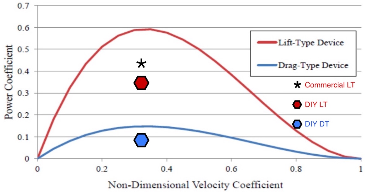
11295-0

Here is the difference in efficiency between commercial and DIY technology:
11296-1

How does the above relate to the subject?
Keep in mind the most efficient wind turbine is an Horizontal Axis type or HAWT. This turbine keeps moving to face into the wind. When there is too much blockage the wind will take the course of least resistance and go around the blockage. Likewise a shelter break of trees becomes a wind block when it is too thick, causing such turbulence that the dumping effect on the leeward side can do damage. When a wind break has good permeability, it slows down the wind for five times the distance of the height of the trees.
Now if we look upwards from the centre of the orifice, all the water must pass through this orifice like wind in a wind tunnel, so better in effect than an open HAWT, but with more swirl to the current. Yet all the GWVPP sort of commercial turbines used currently are a drag-force type of blade! So it appears that this type of water vortex extraction is still in it's infancy or surely it would have advanced to a lift-force blade? The design needs to be very permeable so that maximum energy can be extracted. As the water is so much more dense than air, it's movement over the foil has the same range of Reynolds numbers as a heavy-lift freighter aircraft, glider or long range drone.

“Water has a density of 1000 kg/m^3. If you had a meter cubed of water it would weight about 1000 kg. Air that is near sea level has a density that averages 1.275 kg/m^3. 1000 kg/m^3 divided by 1.275 kg/m^3 yields 784. Therefore, at sea level, air is 784 times less dense than water. Expressed in another way, a volume of air at sea level has 0.1275% of the density of the same volume of water.” Quote from meteorologist Jeff Haby.
A big reason why Pelton type turbines have higher efficiency with high head than other types is the very low pressure area below the buckets. The water is going from high pressure with low volume, to an area of large volume so it can lose the pressure kinetic energy to mechanical power. Water hits the buckets then drops into air space. The Fishway GWVPP has the potential for high efficiency because it has a low pressure column of air at it's centre which becomes absorbed into the draft pool underneath. The device was designed for aeration of waterways before the Austrian engineer realised he could extract power by suspending a turbine in the centre.
Next we should have a look at Tip Speed Ratio (TSR) and how that has effect on this design.
Rgds, Nat
In the multitude of counsellors there is safety...
King Solomon

...almost right? Often almost is not good enough.

Ungrounded Lightning Rod

  • SuperHero Member
  • ******
  • Posts: 2865
Re: Fish-way using low head hydro turbine
« Reply #36 on: May 26, 2018, 12:01:37 AM »
The Betz limit is about extracting momentum from a compressible fluid moving in an environment of more of the same material - in particular, material of the same density.  There you have to leave over 40% of the kinetic energy in the air to get it out of the way of more air if you want to get somewhere near all you could get.

With water you're usually trying to extract the gravitational potential energy from the dense water - in nowhere near as dense air - moving from a high to a low place.  As with lowering a stone on a rope that passes over a winch, you can get pretty close to ALL of the potential energy from lowering the heavy stuff - and raise it almost to the original height.  You may convert it to kinetic energy on the way down, and harvest that.  But if you harvest it so the water is delivered moving very slowly into an unrestricted drainage, you've gotten rid of (mostly by collecting) the potential energy and also left nearly no kinetic energy in the water when you're done with it.

A pelton wheel, for instance, converts the potential energy of the water into kinetic energy by releasing a narrow jet of it through a nozzle at very nearly the drain level, then collects this by reversing its direction in a cup that is retreating at about half the jet's speed, leaving the water essentially stopped at about the surface of the water level in the drain system.  Neglecting inefficiencies from friction, the water is left with enough "lost energy" to fall the remaining short distance to the drain level and flow away, while the rest of the energy does mechanical work on the rotor.

You might find something Betz-ish in something like a propellor or other waterfoil trying to extract kinetic energy from an unconstrained underwater current, wave action, or the like.  But most practical mills are driven by water that is in a constrained passage moving from a higher to a lower level, with most of the energy being from the level change (mapped into a difference between input and output pressure) and very little in the momentum of the wastewater as it leaves the machinery.

Natreely

  • Newbie
  • *
  • Posts: 34
  • Country: au
  • Sometimes I'm always almost right!
Re: Fish-way using low head hydro turbine
« Reply #37 on: May 26, 2018, 04:28:27 AM »
ULR in last post said, "other waterfoil trying to extract kinetic energy from an unconstrained underwater current"
This is exactly the case above the orifice in the rotation tank, and it is often described in scientific papers as a 'free surface vortex'. Except in this case there are three different current directions as previously commented on: converging to axis base flow, rotating around axis spiralling downward flow and the vertically falling surface flow at the air core. Except whereas you say the singular "waterfoil", we need to say water-foils, for in this case there would need to be at least 10 small foils and possibly 14. We will see how the drawings and math stack up. As the water-foils have Betz-ish issues, we need to be aware of where the wake turbulence is going so it doesn't impact on other foils. With a 1.3m diameter turbine there should be room for a decent spacing between foils both radially and vertically. Not likely to try to extract energy from the base flow because this would cause the diameter to extend more, which would increase leverage for little gain (it would also take more research and experimentation to get it right = more $).

"constrained passage moving from a higher to a lower level"
This is also the case, so we can design to take advantage of both the velocity and pressure change. Although at 1.5m maximum vortex height there is not a lot of pressure difference, so the lift-force on the foils should be the greater % of energy extraction compared to the drag-force. Yes, we do accept that water is basically incompressible, although there is a marginal density increase as the temperature decreases, down to 4 degrees Celsius (apologies for technical trivia). As velocity increases, temperature decreases allowing dissolved oxygen to increase also, consequently the DO levels underneath the orifice are much higher than above, causing the resting pool underneath to be very fish-friendly (sorry, more trivia).

Keep in mind we are designing for 3 different flow ranges and resulting vortex heights, orifice diameters and tank effective diameters, as the math shows that outside these specifications it is too difficult controlling turbulence. We want a nice clean laminar flow... just like the preferred air for wind-foils really!
Rgds, Nat
In the multitude of counsellors there is safety...
King Solomon

...almost right? Often almost is not good enough.