Author Topic: BLDC Motor… as a Generator-Alternator?  (Read 11580 times)

0 Members and 1 Guest are viewing this topic.

ronbot

  • Newbie
  • *
  • Posts: 10
  • Country: us
BLDC Motor… as a Generator-Alternator?
« on: February 01, 2015, 04:02:58 PM »
(hope this didn't post more than once... had problems getting it to post)

OK, so I looked and looked for info on the web about this, and it seems I'm treading where no man has gone before… at least, not down this specific path.

My need is for an alternator, phase count is not important (though I do understand the benefits of 3-phase smoothing), but “smallness” is critical. So, I an endeavoring to convert a large/flat “outrunner” style BLDC into a low-speed alternator.

I am trying to find someone who can help me with a rewind… pro's and con's, best output Power at the lowest speed – up to about 300RPM if possible (which is why I posted it here, in the "Wind" board. I figure it may be useful to others here.

What I bought (ouch) to work with is a pair of HobbyKing Turnigy LD9017 Gimbal motors… made specifically for very low rotating speeds, low power, sine-wave drive, high positioning torque. 
http://www.hobbyking.com/hobbyking/store/__53946__Turnigy_LD9017_Brushless_Gimbal_Motor.html

They also sell a version wound with heavy multi-strand wire, made for direct-drive of huge (26”) multi-copter rotor blades… it's rated for 2600 Watts (yes, 3.5HP), 105RPM/V, max. 117A (and this isn't even their biggest one, which is capable of 2800 Watts)
http://www.hobbyking.com/hobbyking/store/__56935__Turnigy_9014_105kv_Brushless_Multi_Rotor_Motor_BLDC_.html

(want bigger? https://www.youtube.com/watch?v=fHDh3IFQ8hY&x-yt-cl=84359240&x-yt-ts=1421782837


The LD9017 spec's: (mostly mfr published, corrected according to ‘real' parts received)
Radial Flux
Poles: 24 Stator poles/teeth; 28 magnet Rotor
KV (RPM/V): 9 (per mfr spec)
Resistance: 18 Ohm's (per 2 windings in series in "Wye" connection)
Wire: 0.27mm with 110 turns
No Load Current: 0.1A @ 14.8V
Motor Dimensions: 90x30mm
Weight: 415g

My additional measurements…
STATOR:
18 layers of 0.5mm steel
(total stator thickness: 9mm + a little epoxy)
Tooth depth: 14.7mm
Total Stator depth (tooth depth plus inner ring thickness): 17mm (seems to be the "17" part of the p/n)
Stator Pole Face: 7.77mm wide (by 9mm thick)
Stator tooth winding width: 4.44mm (by 9mm thick)
Stator Pole Face gap: 2.55mm (between pole faces)
Stator OD: 80.1mm

ROTOR:
Rotor magnet ring ID = 81.17mm
Individual magnets are 10mm tall (slightly taller than 9mm stator poles)
Magnet strength: unknown
Stator/Rotor gap: 0.535mm (81.17-80.1=1.07mm/2)

I made a simple test: (wired in Wye/star fashion)
RPM = 350 (the speed of my cordless drill on low speed)
VAC RMS = 27.4/phase
Raw kV = 12.8

Using a Schottly diode (low Vf) 3-phase bridge rectifier and a 1,500uF cap, my best power so far (stock config.) was:
341 RPM, 15.90V DC @ 1.06A = 16.85 Watts
(349 RPM, no load = 39V DC)

Yuk.

Re-wired as Delta (all else the same):  343RPM, 11.0V DC @ 1.47A = 16.13 Watts.

Will it even do more?  Yes… in Delta, at 1060RPM I get 42V DC at 2.73A = 112 Watts… Nice… but would require much more mechanical drive complication to reach 1,000+ RPM.

Since it's 24-tooth and 28 magnets, I can split the entire motor in-half electrically, and treat it like 2 12/24 machines… so I did. Split the windings in half, paralleled them, and got… the same maximum power (makes sense now, same copper, same wind config, same power… duh)

At best now in “Wye” (Star) I get:
367RPM, 21V DC @ no load  /  339 RPM, 3.62A DC, shorted
347RPM: 9.04V DC @ 1.81A = 16.34 Watts 

Delta wired:
332RPM: 5.83V DC @ 2.16A = 12.59W  (the diode drop is a larger percentage now at these low voltages)

It's currently wound as: Aa bB Cc aA Bb cC (repeat)

I'm not afraid to rewind… but I admit I do not know, nor can I find, what the best winding configuration is for low RPM. I don't care about cogging… I will have plenty of initial torque to drive it (it's not wind turbine… but could be useful for others)

Any generator/alternator “pro's” here?

I considered: AaA bBb aAa BbB – but that can only give me 2-phase with the tooth/magnet ratio, and only about 6-7° out-of-phase.

I've attached an image I found while trolling around… it's essentially this:
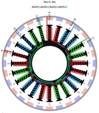
SparWeb

  • Global Moderator
  • Super Hero Member Plus
  • *****
  • Posts: 5452
  • Country: ca
    • Wind Turbine Project Field Notes
Re: BLDC Motor… as a Generator-Alternator?
« Reply #1 on: February 01, 2015, 06:48:04 PM »
Hello Ronbot, and welcome to Fieldlines!
Not used to new members committing so much to their first post, but it's a good question right off the bat.

Rather quickly you've touched upon several concerns that we have, if we take a stock motor and drive it as a generator.  In a wind turbine, there are certain constraints; many apply no matter what will ultimately drive the generator.  It takes many tricks, including re-wiring, altering the flux path (typically adding magnets but not limited to that) and using electronics downstream, not to forget that dumb luck can help.

The Turnigy motor you're got is similar in design to the washing-machine motors from Fisher-Paykel and LG that I've seen used successfully in wind turbines for many years, except that this Turnigy is much smaller than those units, and lacks the driveshaft and mounting flange that makes them more convenient to use, too.

Electrically speaking, you are limited by the winding resistance.  With 18 Ohms per phase I don't see more than the output you've already got, but you can get more - just use a bigger cordless drill.  The Turnigy may get hot.

When using a generator to recharge a battery, the system voltage becomes a limiting factor for the generator's power output.  The 12V battery "clamps" the system voltage to a fairly flat 14V (give or take a volt) during charging, through the rest of the generating power train, including the alternator.  This limits the power that the alternator can produce.  The only factor left is the current.  An alternator that operates in a clamped-voltage system will produce no current until the speed increases enough that the voltage exceeds the battery voltage.  Then increasing the speed delivers a linear increase in current.  The current can be increased by driving it to turn faster (until the alternator burns out).

Will you actually be using the alternator in a battery system?
If not wind, what will be driving it?  How fast, how much power, etc?
No one believes the theory except the one who developed it. Everyone believes the experiment except the one who ran it.
System spec: 135w BP multicrystalline panels, Xantrex C40, DIY 10ft (3m) diameter wind turbine, Tri-Star TS60, 800AH x 24V AGM Battery, Xantrex SW4024
www.sparweb.ca

joestue

  • Hero Member
  • *****
  • Posts: 1760
  • Country: 00
Re: BLDC Motor… as a Generator-Alternator?
« Reply #2 on: February 01, 2015, 07:43:28 PM »
There are only two winding configurations for that combination of magnets and slots.

https://www.emetor.com/edit/windings/

If a reduction in cogging torque is of any interest to you, you can reduce the magnets to 26, and the lcm is doubled from 168 to 312.
but, about the only thing you can do is increase the copper.
A friend of mine may ask me to rewind one of these motors for some engineering project.. he says its only 2/3rds full of copper.
My wife says I'm not just a different colored rubik's cube, i am a rubik's knot in a cage.

ronbot

  • Newbie
  • *
  • Posts: 10
  • Country: us
Re: BLDC Motor… as a Generator-Alternator?
« Reply #3 on: February 02, 2015, 12:38:21 AM »
joestue...

"and the lcm is doubled from 168 to 312"

Would you educate me a bit on the "lcm"? 
(go ahead, be technical... I'm an EE, but never studied motors/generators in-depth)

Thanks for the link... it's a help.

I like the 2 level winding... it makes more sense than the one I mentioned... I've never thought of winding multiple phases on a tooth. However, when a specific tooth has both "W+/W+" on it, does that indicate twice as many turns of the same phase-wire... as opposed to the teeth that are shown as "W+/V-" ?  In other words, all teeth have the same amount of copper... just that some teeth are shared, some are not?

What would the pro's and con's of this type of winding be?

Thanks!!

joestue

  • Hero Member
  • *****
  • Posts: 1760
  • Country: 00
Re: BLDC Motor… as a Generator-Alternator?
« Reply #4 on: February 02, 2015, 01:31:27 AM »
Winding each slot separately reduces the end turns and reduces the winding resistance just a little bit. For a short winding height the decrease in resistance may offset the reduced voltage (.933 instead of .966) and in your case i think this is true. However it is more complicated to wind and sometimes its easier to fit more copper in the machine winding every other tooth.

LCM is least common multiple, its simply the number of positions the magnets will stick to, higher = lower cogging torque generally.
My wife says I'm not just a different colored rubik's cube, i am a rubik's knot in a cage.

Rofl

  • Newbie
  • *
  • Posts: 2
  • Country: no
Re: BLDC Motor… as a Generator-Alternator?
« Reply #5 on: June 16, 2015, 02:36:06 AM »
I have a project involving generating power with a Turingy 9017 - 105kv. But i think i ran in to a big problem. The rpm of the system wich is going to drive the generator is varying from 1000 to 7000 rpm. with normal running speed at 5000rpm.
Max voltage of the motor is 22v so this is way beyond spec rpm (2310rpm).

The motor was not chosen for this project, it was just a spare part i found.
 
My question: Is there any way i can increase the kv of the motor?
Or is there any other way i can get this to work without using a gearbox.
Maybe if its possible disconnect some poles or something.
If no, does anyone have any gearbox suggestions?

joestue

  • Hero Member
  • *****
  • Posts: 1760
  • Country: 00
Re: BLDC Motor… as a Generator-Alternator?
« Reply #6 on: June 16, 2015, 05:23:18 AM »
if the iron core is not overheating, the only thing you have to worry about is the bearings, and they can probably handle it. hoop stress in the steel cylinder is probably not a problem.

increasing the kv will increase the voltage.. the "maximum voltage" of the motor is of no concern. 22 volts won't break the insulation down.

given that many of these motors have a dozen strands of insulated wire, you can simply re-solder the connections to double the voltage, which would multiply the reistance of the winding by 4.
if you have an odd number of strands greater than the number 7, i would not worry about it, just split it evenly.

you can also change it from wye to delta but these motors may have circulating current problems.. so keep that in mind. it probably won't be a problem because these motors have relatively high leakage inductance.
My wife says I'm not just a different colored rubik's cube, i am a rubik's knot in a cage.

Rofl

  • Newbie
  • *
  • Posts: 2
  • Country: no
Re: BLDC Motor… as a Generator-Alternator?
« Reply #7 on: June 16, 2015, 07:10:22 AM »
Thanks for the response!

If i'm calculating this correctly i will get about 47.5V at 5000rpm when the kv is 105, right?
And 66.6V at 7000rpm. So this is alot more than the max voltage spec of 22V.
Will that not be a problem for the insulation or an i missing something?

And what do you mean by resoldering to double the voltage? Do you mean double the maximum voltage of the motor?


http://www.hobbyking.com/hobbyking/store/__56935__Turnigy_9014_105kv_Brushless_Multi_Rotor_Motor_BLDC_.html

joestue

  • Hero Member
  • *****
  • Posts: 1760
  • Country: 00
Re: BLDC Motor… as a Generator-Alternator?
« Reply #8 on: June 16, 2015, 12:58:10 PM »
Thanks for the response!

If i'm calculating this correctly i will get about 47.5V at 5000rpm when the kv is 105, right?
And 66.6V at 7000rpm. So this is alot more than the max voltage spec of 22V.
Will that not be a problem for the insulation or an i missing something?

And what do you mean by resoldering to double the voltage? Do you mean double the maximum voltage of the motor?


http://www.hobbyking.com/hobbyking/store/__56935__Turnigy_9014_105kv_Brushless_Multi_Rotor_Motor_BLDC_.html


heh, i just realized how much work that would be..
if you really want to try that.. you have to desolder the wires and separate each individual strand.
you then have to take half of them, and connect them back in series with the other half, then resolder the wires to the end, do this for each phase.
that will double the voltage. however, its a lot of work

the max voltage limit of the motor is most likely an rpm limit, they do not want you overspeeding the motor and blowing up the propeller. or breaking the steel band which holds the magnets in.
at 7000 rpm that will be a pretty violent event..

at those rpms the frequency will be very high and so will the losses in the iron core.
My wife says I'm not just a different colored rubik's cube, i am a rubik's knot in a cage.