Author Topic: CFL inverter. Yes another one.  (Read 15593 times)

0 Members and 1 Guest are viewing this topic.

commanda

  • Hero Member
  • *****
  • Posts: 731
CFL inverter. Yes another one.
« on: December 13, 2007, 12:56:49 AM »
This is something I mentioned here on FL quite some time ago now; using the main transformer out of a pc power supply, and running it "backwards" to generate a high voltage for driving CFL's.


The original secondary winding centre tap goes to positive 24 volt supply. Fet to ground off each of what used to be the 12 volt taps.

The original primary winding now becomes the high voltage output. In this case I used a voltage doubler rectifier, and set the feedback voltage divider to give an output of 240 volts dc. The controller chip is an SG3525, running at 50KHz, although you could use the TL494 salvaged from the same junked pc power supply; although you'll need to add the totem pole driver stage for each fet. Output voltage remains near enough to constant over an input voltage range of 20-30 volts, tested driving an 18 watt 240 volt cfl. Side by side testing using a matched pair of 10 watt lamps, one driven off this inverter, the other plugged into the 240 volt mains, shows a barely discernable light intensity advantage to the mains powered lamp. I'm also powering the controller chip off a 7812 regulator, which does need a small heatsink.


A 12 volt powered version could be built, though you would probably need to connect the fets to the 5 volt taps rather than the 12 volt taps.


The circuit is similar to that published in Silicon Chip magazine in September of 2004, which is also available from Oatley Electronics as kit 111b for AU$27.00.


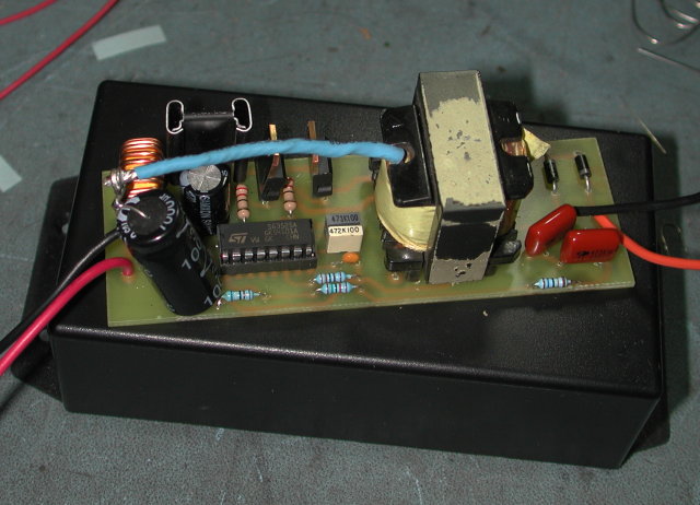
I did the pcb layout to slide neatly into a UB3 jiffy box. It goes in vertically between the posts which the lid screws to, and needs no additional hardware to hold it. The jiffy box has a flanged lid for mounting. I will probably make several units with 2 lamp holders attached directly to the ends of the jiffy box, one each end. Then screw the jiffy box to a piece of 3 inch wide timber painted white, and call it a lamp fitting.


This particular board is a little rough; it is a prototype after all. I have re-done the layout to tidy up all the little changes, but haven't etched a new board yet.


I've been saving old power supplies for quite some time now explicitly for this project, and have about a dozen of them.


Amanda

« Last Edit: December 13, 2007, 12:56:49 AM by (unknown) »

BT Humble

  • Sr. Member
  • ****
  • Posts: 475
Re: CFL inverter. Yes another one.
« Reply #1 on: December 12, 2007, 07:08:20 PM »


I've been saving old power supplies for quite some time now explicitly for this project, and have about a dozen of them.


Want some more?  I've got a recycling tub full of them, and a shoebox full of ferrite transformers from others that I've dismantled... ;-)


BTH

« Last Edit: December 12, 2007, 07:08:20 PM by BT Humble »

commanda

  • Hero Member
  • *****
  • Posts: 731
Re: CFL inverter. Yes another one.
« Reply #2 on: December 12, 2007, 09:12:47 PM »
I would contend that they're probably not worth the cost of freight. I've currently got about 2/3rds of all I'm ever likely to need. But thanks for the offer.


Gotta relate a funny story. At lunchtime I thought I'd take the opportunity to dismantle the collection of dead psu's under the bench. After doing this, I returned to my computer desk to a blank screen. After the usual checking of the obvious, I trundled off and rounded up a replacement power supply.

So now I've got another dead psu to dismantle.


Amanda

Truth is stranger than fiction at times.

« Last Edit: December 12, 2007, 09:12:47 PM by commanda »

BT Humble

  • Sr. Member
  • ****
  • Posts: 475
Re: CFL inverter. Yes another one.
« Reply #3 on: December 12, 2007, 09:21:13 PM »


I would contend that they're probably not worth the cost of freight. I've currently got about 2/3rds of all I'm ever likely to need. But thanks for the offer.


You're quite right.  However, if you're planning to attend next year's Unaugural (May 3rd) then you're welcome to them. ;-)


BTH

« Last Edit: December 12, 2007, 09:21:13 PM by BT Humble »

spinningmagnets

  • Hero Member
  • *****
  • Posts: 600
Re: CFL inverter. Yes another one.
« Reply #4 on: December 12, 2007, 09:33:11 PM »
After reading your post twice, it still sounds like Chinese calculus to my spongy old brain, but I'm grateful for the info being saved here, for when I need it later.


You had me at "..running it backwards...salvaged...junked..."


Only thing I can suggest is to put "free" somewhere in the title, to draw the attention you deserve! Good on ya, mate!

« Last Edit: December 12, 2007, 09:33:11 PM by spinningmagnets »

commanda

  • Hero Member
  • *****
  • Posts: 731
Re: CFL inverter. Yes another one.
« Reply #5 on: December 13, 2007, 07:33:55 PM »
Just for completeness, here's the circuit diagram.


http://www.otherpower.com/images/scimages/2006/0135_001.pdf


Amanda

« Last Edit: December 13, 2007, 07:33:55 PM by commanda »

commanda

  • Hero Member
  • *****
  • Posts: 731
Re: CFL inverter. Yes another one.
« Reply #6 on: December 21, 2007, 08:32:57 PM »
And one last photo of the pcb inside the jiffy box.


Fuse on the incoming dc has an led and resistor across it so if the fuse should blow the led will come on.


Notches in the corner of the pcb are to clear the moulding in the lid of the jiffy box.

This is now the second one I've built. Both been running all day every day for a while now. Side of the box runs slightly warm to the touch, about 40 deg C. Most of this comes from the 12 volt regulator. If building these for a 12 volt system you wouldn't need that regulator at all. Might even change the regulator to 15 volts.

Still refining the pcb layout; should have it perfect for the third unit. I haven't uploaded the layout as yet, just ask if anyone wants a copy.


Amanda

« Last Edit: December 21, 2007, 08:32:57 PM by commanda »

candel light

  • Newbie
  • *
  • Posts: 1
Re: CFL inverter. Yes another one.
« Reply #7 on: September 14, 2008, 10:25:59 AM »
A question! The original design from Silicon Chip produces 360V DC, while yours one 240. Why is the difference?
« Last Edit: September 14, 2008, 10:25:59 AM by candel light »

commanda

  • Hero Member
  • *****
  • Posts: 731
Re: CFL inverter. Yes another one.
« Reply #8 on: September 17, 2010, 05:10:56 PM »
belated update.

Since I've now gone with a 12 volt battery, I've modified my 6 units to run off 12 volts. Removed the 7812 regulator, and changed the taps on the transformer I'm connecting the fets to. Running a 13 watt cfl, the fets with no heatsink see about 15 degC temperature rise.

And to answer a question. The output is set to 240 volts, not 340, because of the turns ratio of the transformer. 240 volt cfl's work just fine on 240 dc.

Amanda