I got the Idea for this design from a friend, from here on known as Dan. He is a great guy, lots of interesting Ideas just not mechanically inclined. This is where I come in to play.
The concept I worked from was a US patent, now expired. It is combination of an inner rotor and outer ring of angled stationary blades. Pretty simple right? Whell it wasn't as simple as I thought considering all I had to work with were pics on a patent.
The Inner turbine from the patent consists of 8 “Lâ€, 90 Deg., shaped blades. The inner point of the blade pointing to the center of the turbine. That was pretty easy to figure out how to construct. So I made 2 inner turbines. 1 using the “L†shape blades and 1 using 6†x 1/8†wall, Sch. 40 I think, PVC cut into 1/3's. I tested both and decided to go with the PVC cup blades.
The outer ring of blades consisted of 36 evenly spaced flat blades angled to direct the wind at the inner blades. The angle of the blades in a circle created a venture affect. Low pressure to high pressure in and high pressure to low pressure out. This also created a cavity that could only handle a given volume of air flow. Once this volume capacity is reached the air no longer enters the turbine and goes around the turbine. There is a maximum velocity for the inner turbine. I haven't figured out what that is yet for my 27†by 27†turbine.
I strapped the completed turbine in my truck and got it up to 80 mph and was still climbing. I didn't need a ticket so I slowed down. But I'm getting ahead of myself.
I tried several different blade designs for the outer ring. A flat, wedge and double wedge. I researched wing designs and decided to go with the double wedge. I got the highest velocity spin with the inner turbine using this design.
Tools used for the construction. A table saw, drill press and E-machineshop. The wind source was a small 3 speed Stanley blower. And a bicycle odometer calibrated to the size of my inner turbine. The odometer was a very helpful and cool idea I found on the net.
I used the drill press like a router to make all the round parts with a 1/8†dremel bit. Top, bottom and inner blade supports and blade slots. It took a bit to figure that out. E-machine shops was very useful in making the templates I followed to cut out the inner blade slots and the layout for the inner and outer blade positioning.
The outer blades I made from 3/4†Oak flooring left over from work. They haven't warped yet so it was a good choice. 3†wide, 1/8†at the tip and approximately 5/8's†in the center. This created a wide opening on the out side and from the middle of the blade in almost a straight line to the inner turbine. A venture effect that worked well for me. The pivot point of the blades is in the center. Once I got all of these into position came the adjusting stage for max spin of the inner turbine. This took for ever to get too. I used 1/8th†to 1†hole bits to do the adjusting of the outer blades. Yes got a stating point and laid out a patter for all 36 blades and started adjusting one bit at a time. It took for ever but I got it done, 3 months later, a few hours at a time. The odometer was the tool for this process.
Now I have a working Turbine. Next.... the alternator.
Having no clue how to do this, back to the net. I read and read and read. At the time there was not a lot of info on VAWT alternators lots on HAWT. I bought a Book from Hugh Piggott and used his alternator designs to make a 12v and 48v 9 coil duel magnet rotor single stator alternator, direct drive. The 48v worked the best but I could only get 12v in a 12 to 15 mph wind. This just wasn't going to work in Seattle, with an average wind of 5 mph except for stormy days where I lived at the time. I tried using pulleys to gear up the alternator but the cogging made it even harder for the turbine to start spinning.
Back to the patent and the alternator used with this turbine. Using Emachineshop I worked out the approximate size of the alternator used with this turbine. Over 4' across with over 200 -1†x 2†x 1/2†magnets. Domino sized is what it said in the patent.
I have, in the last few months, started working on my project again. I'm 6 or 7 years into this project now, a lack of funding and building a mill put the turbine on the side lines. I'm slow and steady.
The Alternator.
It consists of 1 aluminum magnet rotor, center, with and 2 stators on either side. The stators consist of 360 slots with 3 leads stacked, of magnetic wire in a 3 phase configuration, in a serpentine pattern. This design does not down scale easily. I have been able to get it down to 19†using 1/2†x 1†x 1/4†N45 neo magnets. Wire size was the determining factor for the 19†rotor. I'm using #16 magnetic wire, mainly because I have a roll I bought and never used. The magnets are set in the rotor stacked 2 per slot, N, S, N around the disk. The wire is evenly spaced around the stators at 1 deg, Phases staggered every 3 slots to get 3 phase. 1 Phase under every magnet. The magnet separation is about an1/8th†at the closest points. Since I don't have a CNC yet this is going to be a lot of fun to build. The patent states that a gear box was used to increase the rotor speed. Basically it is a magnetic levitation design used to make power, not to move things. I've been reading up on metal casting and mold making. This is an inexpensive alternative to paying for a machine shop to make them. Between work and Dan I have every thing I need to accomplish this task. Back to the table saw.
Note: This was patented in the 80's, 20 years after he had already built this alternator and turbine and put it into use.
So here is my dilemma, more learning required. I still can't, for the life of me, put my head around this math for figuring out alternators. I don't want to just build it and hope it works. I don't have the money for that kind of learning. You know, I have to ask the right question to get the answer. 42?
I do Understand some of the basics for the coil style alternators. This one is just baffling. I will eventually just build it, I always do, I would just like to understand more on how it works before then.
Whell there you go for now. Any input on understanding alternators is greatly appreciated.
Unlike HAWT, which you can find detailed information on construction, start to standing. The detailed information for the VAWT is very allusive, especially the alternator, or generators used. A piece here a piece there, but nothing all together.
turbine alternator

Outer blades

Inner Turbine

direct drive Alternator

indirect drive alternator

Painted turbine complete

on the roof

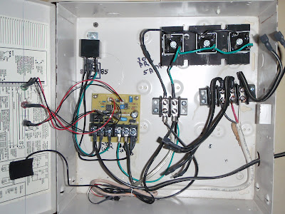
charge controler
alternator attached

charg controller

