Author Topic: pipe based furling mechanism  (Read 3739 times)

0 Members and 1 Guest are viewing this topic.

Chuck

  • Jr. Member
  • **
  • Posts: 77
pipe based furling mechanism
« on: July 28, 2003, 12:13:16 PM »
One drawback to some of the best plans available for wind generators is a requirement for welding. I agree that this is a great way to build a sturdy platform, but many of us don't have the required tools or skills to pull it off. I've puzzled over the problem for a while now and this weekend I put some form to some of my ideas.


The idea is to create a side furling mechanism using readily available parts without having to resort to welding. Furthermore, I wanted something adjustable since I wanted to experiment with getting the right angles. The readily available parts are 1 1/4" black water pipe 45 degree and 90 degree elbows, two "T" joints, some reducers (1 1/4" to 1/2"), a 3/8"x6" black pipe with caps and a few 1/4" bolts. The tail boom is 4 feet of 3/4" square tube and there is some 1/8"x3/4" flat galvanized bar stock.


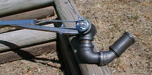
The first view shows how it looks from above. This shows the positions of the 45 and 90 degree elbows. Note that none of these photos show the 1/4" bolts inserted through the joints required to keep them from unscrewing from the weight of the tail.


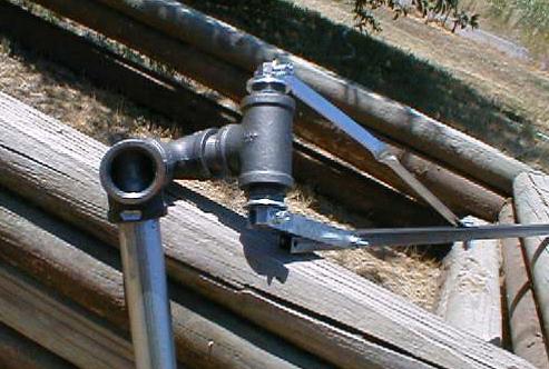
The next view is from the side where the generator attaches to the hole on the left of the photo. I use a floor flange for this... I'll try later to get some photos of the whole assembly. My camera was low on batteries this weekend.


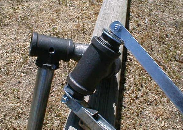
Here is a close up of the bearing assembly. It's a 1 1/4" T pipe with reducers at each end to reduce the opening for a 1/2" pipe. This fits a 3/8" pipe quite nicely. A few 5/8" washers give it a larger bearing surface and reduces slop. Holes drilled through the caps allow 1/4" bolt connections to bar stock which holds the tail boom. The bar stock is twisted to give the tail it's vertical orientation. The hole drilled in the main "T" is intended for a thin nylon rope which can be used to pull the tail in a locked furled position. The smooth bearing surface isn't in place in the photo.


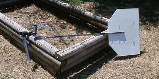
And finally the whole thing showing the tail. The bolts locking the joints into position are not shown on any of these photos. I did that after the camera batteries gave out. It's easy to envision though. Each joint has a 1/4" hole drilled completely through the large collar and a 1/4" bolt is inserted through it with a lock washer and bolt. Super glue or locktite finishes the locking of the joints. I didn't get a chance to raise the unit yet as the new blades haven't been balanced yet and I wanted to beef up my tower raising gear first. More to follow...

« Last Edit: July 28, 2003, 12:13:16 PM by (unknown) »

windstuffnow

  • Hero Member
  • *****
  • Posts: 1065
  • Country: 00
Re: pipe based furling mechanism
« Reply #1 on: July 28, 2003, 06:40:10 PM »
  Chuck,  It looks like a pretty ingenious idea. I'm not sure how you plan to mount the generator/alternator but the way it sounds you plan to mount it center of the mast mount ( the hole on the left).  This will make the gen/alt centered and the furling tail will have no effect.  The gen/alt has to be mounted offset from the center of the pole piviot.  You may have already figured this out but its just an observation of how it was explained.  Minor detail in any case.... good work... let us know how it works out


Have Fun

Ed

« Last Edit: July 28, 2003, 06:40:10 PM by windstuffnow »
Windstuff Ed

DanB

  • Global Moderator
  • SuperHero Member
  • *****
  • Posts: 2151
  • Country: us
    • otherpower.com
Re: pipe based furling mechanism
« Reply #2 on: July 29, 2003, 08:11:41 AM »
Neat Chuck - it's nice to simplify things like this!  Be fun to see that when she's done....

« Last Edit: July 29, 2003, 08:11:41 AM by DanB »
If I ever figure out what's in the box then maybe I can think outside of it.

Chuck

  • Jr. Member
  • **
  • Posts: 77
Re: pipe based furling mechanism
« Reply #3 on: July 29, 2003, 09:09:59 AM »
Hi Ed,


I guess the pictures and/or text are misleading. The "T" over the mast is oriented horizontally. The generator is mounted on a floor flange that is on the opposite side of the "T" from the tail assembly (flange mounted vertically). Generator on one side, tail on the other, mast inbetween them.


The closest to mast center I seem to be able to get it this way is with the prop centered at 8 inches to the left of the mast (looking from behind), while the tail is on the right. I have had this machine up before with a different tail arrangement and it worked fine. Too good actually as it furled earlier than I wanted it to. This is probably due to the 8" off center distance. Since I can't really change that (it's a big generator) I'll have to deal with tail weight, length, angle etc. to get it to furl efficiently.


If the "T" was mounted vertically it would be as you mention with the generator on top and you could stick a tail out the rear. But of course it wouldn't be a furling setup. Envisioning this brings up some intriguing possibilities though...A dual tail arrangement could be very easy to set up this way... Much simpler, although most folks don't like the looks of a dual tail... You could also use a platform on top that allows the generator to be adjusted various distances from mast center...


Thanks Ed, a totally different angle I hadn't considered.


Chuck

« Last Edit: July 29, 2003, 09:09:59 AM by Chuck »

hvirtane

  • Hero Member
  • *****
  • Posts: 712
    • About Solar Cooking
Re: pipe based furling mechanism
« Reply #4 on: August 01, 2003, 03:10:10 AM »
Hello,


A really nice design.

Thank you a lot for the idea.


I would like to see rough drawings of this design.


I think that this desgn would become one of most

copied designs of the general layout of small wind turbines available, if you would make rough drawings of it.


A very nice feature of this design is that it

is easy to experiment with different angles,

if you will use pipes.


- Hannu

« Last Edit: August 01, 2003, 03:10:10 AM by hvirtane »

Norm

  • Hero Member
  • *****
  • Posts: 1841
  • Country: us
  • Ohio's sharpest corner
Re: pipe based furling mechanism
« Reply #5 on: August 02, 2003, 11:19:22 AM »
   Right on Chuck! Altho I can weld it's a grind a lot weld a little deal.Also gives me something else to 'shop around' at yard and garage sales!

(:>) Norm.
« Last Edit: August 02, 2003, 11:19:22 AM by Norm »

Seth

  • Newbie
  • *
  • Posts: 25
Re: pipe based furling mechanism
« Reply #6 on: August 20, 2003, 11:01:10 AM »
got any more pics yet ????
« Last Edit: August 20, 2003, 11:01:10 AM by Seth »

Chuck

  • Jr. Member
  • **
  • Posts: 77
Re: pipe based furling mechanism
« Reply #7 on: August 20, 2003, 11:43:47 AM »
Well, there's the part 2 pipes diary by me and also the following from LowTechWreck who is using this for his first wind genny.


http://www.fieldlines.com/comments/2003/8/16/61029/3914?pid=9#10


I hope to get some pictures of the finished project up soon. It is up and flying, but I was in a hurry and didn't take photos. I'll be reducing the weight on the tail and will take photos then.


Chuck

« Last Edit: August 20, 2003, 11:43:47 AM by Chuck »