Finally I can stop spending money and start making Free Power.
About 2 years ago I decided I wanted to make a generator for electricity that would supplement the power I was getting from my 12 watt Solar panel. After a coupla days searching I discovered WonderMagnet / Otherpower / Fieldlines and haven't stopped learning yet. It's OK to laugh occasionally as you see my uneducated decisions surface in my discriptions
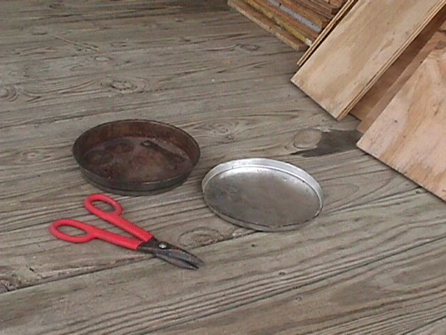
I collected parts for a year before I actually started construction, starting with the Rotors. The first bad idea was to use Cake Pans for the rotors, cutting most of the sides off before gluing the magnets. As you can see, one of these pans has been used to make biscuits.
Then I mounted these Flange type items to the cake pans. These are designed to screw down onto the rod that the rotors will slide onto. I got these pieces at Grainger but I can't remember what they are called, I had to drill the holes for the screws to go through. My second bad Idea was that these Flanges should have been mounted on the other side of the pan.
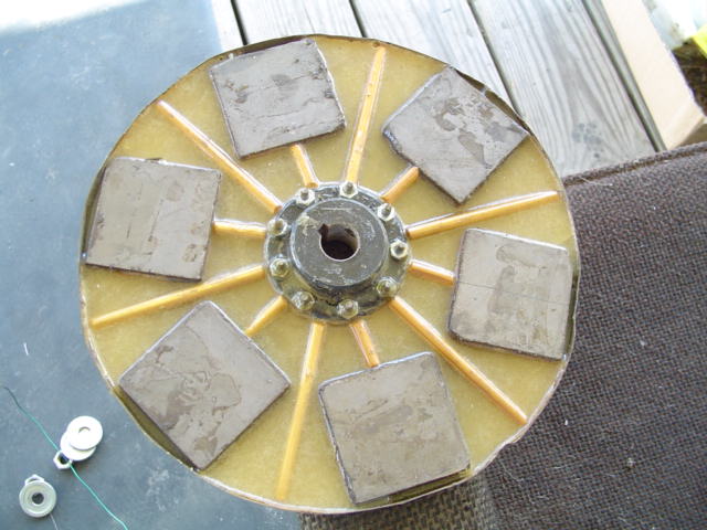
The magnets are 2" x 2" x 1/2" Ferrite that I got at a Ham Fest for 50cents each. Thes are very strong and quite difficult to slide apart when stacked together. I used the 90minute epoxy glue because it's stronger and gives plenty of time to arrange things before it starts to harden. Poured the glue into the pan and started adding magnets. I had arranged the magnets into the pan before with no problems. But this time with the liquid glue in there, the magnets were sliding and jumping all over the place as the glue was acting like a lubricant. I quickly found enough clamping devices and got everything under control.
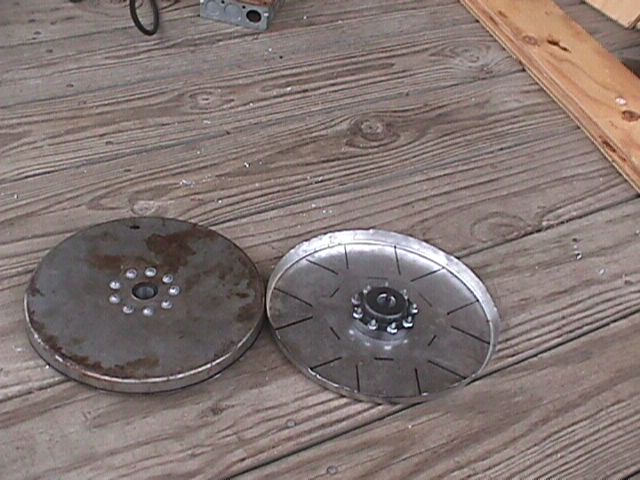
I got concerned about the strength of the cake pans and later poured more Epoxy in there with Wooden ChopStix to stiffen it up some more. Well it was still physically too weak and too much magnetic flux was leaking out of the back, so I cut out 4 sheet metal disks and glued 2 of them to the back of each rotor. It could still use more but it's OK I think.
I tried many different sizes & shapes of coils. Just cut 1/2 inch plywood to the size of the hole in the coils that I need and two larger pieces to hold the wire in. Bolt the 3 pieces together. It helps to cut some slits in the larger parts of this jig so you can get some string in there and tie it all together before unbolting it to remove the coil.
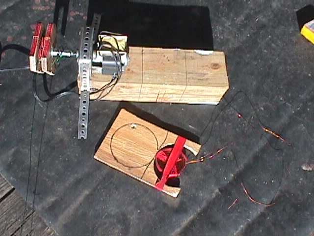
Hand winding coils does not produce a very uniform wind, so I built an electric coil winder. Got an electric motor from an old Disco Spinner Light (15 rpm). Bought a Coupler for Threaded Rod. Drilled the threads halfway out, And epoxied it to the shaft of the motor. Now my plywood Coil Forms screw directly to the shaft of the motor. It's not any faster but it's easier and makes a much better wound coil. No Turn Counter yet, I have painted one edge of the Coil Form red and count it everytime it goes by. I made the coils with 125 turns and it took about 9 minutes each.
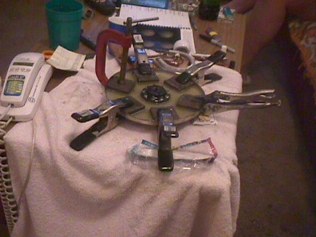
Sitting next to the motor in the picture is my jig for holding the coils in the Airgap of my dual rotor machine for testing.
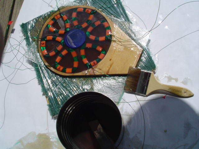
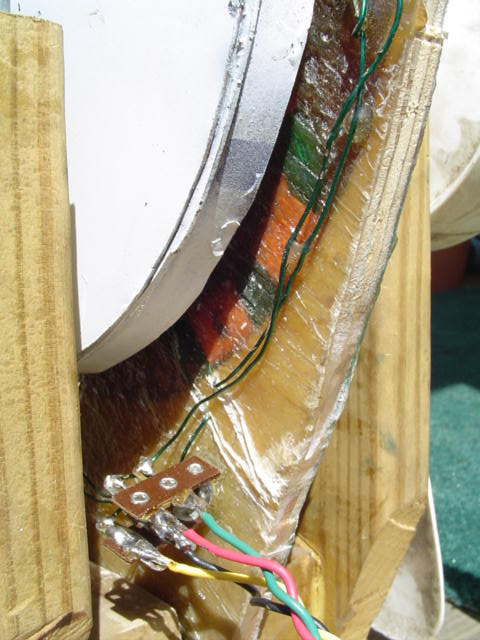
For the Stator I used a piece of plywood that I had cut for the stator, then cut out a hole in the center to pour the coils into. The 6 coils are 125 turns of 19 ga. wire. All the coils are exactly the same and the numbers are just the order in which I wound them. Here is a story talking about the coil/magnet shape/spacing.
http://www.fieldlines.com/story/2003/12/7/225257/916
I painted both sides of fiberglass reinforcing material with the liquid resin and placed it down on one side of my Press (shown Below). I placed a plastic jar lid down in the center of the coil area to reserve space for the shaft between the rotors to pass through. Then poured a small amount of liquid resin into the space the coils were going to be placed. I painted the resin on both sides of the coils and placed them into the resin around the lid taking care to make sure that all the coils were oriented the correct direction. Then I poured more resin in until the well of the mold was full. Lastly I painted both sides of another fiberglass reinforcing sheet and placed it over the whole stack followed by the otherside of my Press.
I cut out 2 plywood squares and 2 carpet squares to press everything together while the Fiberglass Resin hardened. The carpet & plywood were wrapped in kitchen plastic wrap to keep the Resin from sticking to it. With everything sandwiched together between the press halfs, I piled up a buncha transformers on top of the press to keep it all flat and tight together. at that point I slept for 3 hours.
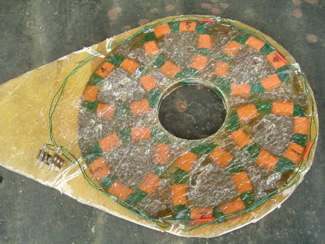
When I woke up I was excited as I unpiled the transformers and pulled apart the press halfs to reveal a near perfect formed stator which did not require a lot of cutting and trimming to get the resin off. I had expected the Kitchen Plastic wrap to stay glued to the resin, but was surprised that it peeled right off leaving the face of the resin exposed. The jar lid was a breeze to remove and made a perfect center hole for the rotor shaft to pass through.
I wired the coils as 1-3-5 in series, and 2-4-6 in series, this gives me 2 sets of 3 coils, measured 1.1 ohms on both sets.
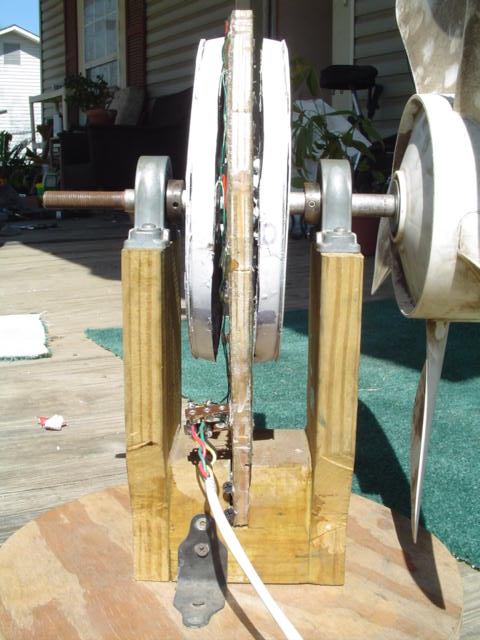
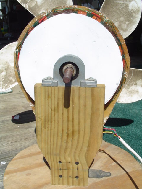
I painted the two rotors white to help protect against moisture and condensation, and then puzzled it all together. I could get it to spin OK at times but the airgap was too small and was rubbing a little. When I cast the coils for the stator I had allowed some of the wiring to stick up a little bit as they came off the edge of the stator. I was disappointed to have to increase the gap but took it all apart and added another 1/8" thick washer and put it all back together. Things lined up really well after that and Testing Began.
I was so happy to finally get this thing put together after almost 2 years since I started cutting cake pans, and anxious to see how much electricity I could make with it. I have a Bridge rectifer filtered by 50,000mfd capaciters feeding 3 amps of 12volt lights with a digital multimeter across the lights.
Measuring one set of coils (1-3-5) getting Bright lights and 12volts at 180rpm.
With all 6 coils in series I'm getting 12 volts at 90rpm
Guess i did'nt have to worry about that airgap afterall.
This is better than I thought I was going to get, I was aiming for 12volts at 240rpm from one set of coils, and at 120rpm for the sets in series. With no load there is almost undetectable cogging and with the 3 amp load on there the cogging was very smooth, not bad at all at 180rpm. The frequency comming out of this genny is quite low, at 180rpm the electric frequency is 9 hertz. The lights flash a lot without the high value capaciters, digital meter did'nt work to well eather.
Now on to the weatherproof housing . . .
]- W o o f -[
