The general construction of axial
alternators will be discussed
in more details later.
This post concerns mainly
the geometry and the wiring of the coils.
1)
You will use some kind of steel
for the magnet rotor base(s).
The geometry is the same,
if you will make a single
rotor alternator with laminates or
a dual rotor alternator with two
magnet rotors.
- what thickness? The thickness should be that big that you cannot feel the magnets using an iron piece from the other side when they are fitted on the other side.
2)
Axial generator coil layouts with 16 magnets.
It is important that the coils are so big in dimensions that the magnet row can fit inside the coil, when the coil is just on the top of a magnet row. Otherwise the coil loops will cancel each other.
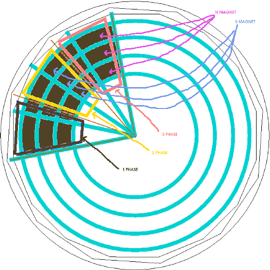
Figure 1.
This picture is to show how you can use small magnets to make of them in effect bigger magnets.
3)
As concerns the number of coil turns. I think that the best way is to make test coils. I cannot know the details of your magnets and the laminates so this is the only way.
- You should wind a test coil of a thin wire, fix it for testing on the stator disk.
- Please see the picture here.
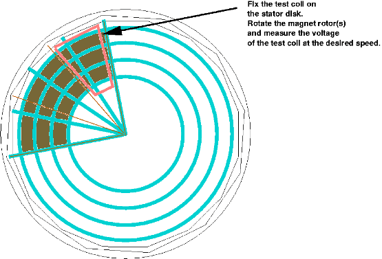
Figure 2.
How to use a testing coil for getting the turns of the coils right.
- Then you will rotate your magnet disk on the top of the stator disk at the desired cut in speed and measure the voltage.
The voltage will rise linearly according to the number of the turns in the coil. The coil wire thickness has no effect for the voltage. A thin wire cannot transfer much current, however.
- Basically. if your wind rotor is going to be 3,6 m - 4 m in dia with 8 blades, for the wind speed 5 m/s, I would make the generator cut in speed to be about 40 RPM.
- If your one coil will reach 2 V at 40 RPM you will get this desired result.
( 4 x 2 V) x 1,73 = 13.84 V.
But this is the case, if wired in 'star'.
With 'delta' wiring you will need about 3,5 V for one coil:
4 x 3,5V = 14 V.
-
If 'star' or 'delta is better... it is a quite difficult matter. Because in principle in 'delta' you can get the better power with higher speeds, but you will need more wire to get the voltage to rise enough high at low speeds. That results with higher resistance (and the coils getting hot) at higher speeds.
In practice some people prefer 'delta', some people prefer 'star'. The best method would be to have a switch to change from 'star' into 'delta' at the certain speed, when the voltage has risen up to the point so that 'delta' wiring can charge the battery.
4)
To see, how to make the connections in 'delta' or in 'star' please see figures below.
- You can make the coils of the thin wire as used for testing by using many thin wires parallel in a coil to get them suitable for higher power.
Please see the excellent explanation by Ed Lenz:
http://www.windstuffnow.com/main/3_phase_basics.htm
And a good story about coil testing is here:
http://www.fieldlines.com/story/2004/4/2/92914/49756
Please see also:
http://www.otherpower.com/otherpower_wind_tips.html
http://www.fieldlines.com/story/2004/3/26/172829/368
- You can afterward experiment with using either star or delta wiring, to get your generator matched better, because it is impossible to know beforehand the speed of your wind rotor.
If possible. I think that it would be better to use 'delta'.
In the following pictures I'm assuming that the magnets are made of one piece.
5)
A picture showing the general layout of the generator.
All the angles needed for this layout can be made by compasses and a ruler, because 360 degrees /12 = 30 degrees (= 60 degrees/2) and 360 degrees/16 = 22,5 degrees (= 90 degrees /4).
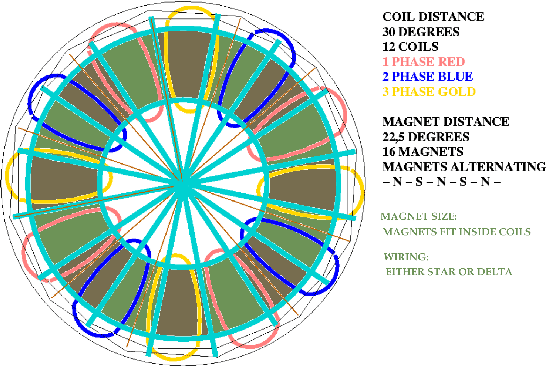
Figure 3.
The geometry of the generator showing the angles.
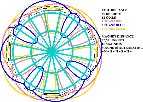
Figure 4.
This figure shows how the coils in each individual phase are connected together. In this layout in each phase the individual coils are connected so that the first coil's 'wire in' is let to be free (for the connections as described below) and the first coil's 'wire out' is to be connected to the second coil's 'wire in', and the second coil's 'wire out' to next coil's 'wire in'... IN - OUT - IN - OUT - ... To be sure that the connections are correct, please measure in a test bench that the voltage is rising in each case when you connected one more coil. If you cannot use a voltage meter, you can feel a wrong connection, if the magnet rotor(s) become suddenly much harder to turn.
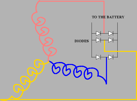
Figure 5.
'Star' connection of the coils. Diodes can be bought from electrical shops. Good usable diodes can be get from car alternators. As second hand they are not costly. Diodes must be checked that they can stand the voltage and the current coming out from the generator.
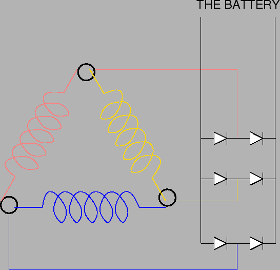
Figure 6.
'Delta' connection.
---
In principle the best power from your alternator can be get, if you'll rectify all the phases separately. But in some cases diodes are costly and if you want to put the diodes on the ground you'll also need more wires. The following picture shows the wiring, if you'll rectify all the phases separately.
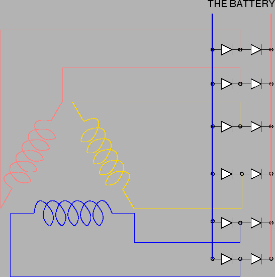
Figure 7.
All the phases rectified separately.
6)
If you will lay the coils on the sides of each others as in the above pictures, it is not easy to get the air gap small. This is because you cannot get many coils on the ring, only 12 in this 16 magnets layout.
7)
Another way is to use stacked coils so that the coils of the different phases are partly laid on the top of each others. Naturally this will lead to another difficulty: how to get them neatly stacked so that the air gap will not again become big. Stacked coils for 16 magnets, three phase layout will look like in the picture below.
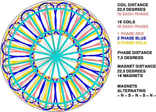
Figure 8.
Stacked coils for 16 magnets and three phase.
The wiring will be the same as in the pictures 4. - 7. above for 'star', 'delta' and 'rectified separately'

There are basically two well-known ways how to make the coils in practice. One method is to make every coil in a jig separately and then connect them. The other method is to use the so-called 'wave-winding', which makes all the coils in one phase at the same time.
Wave-winding is especially suitable for stacked coils and it is generally used with car alternators, for example. Here is the principle of the wave winding of one phase for six magnets.
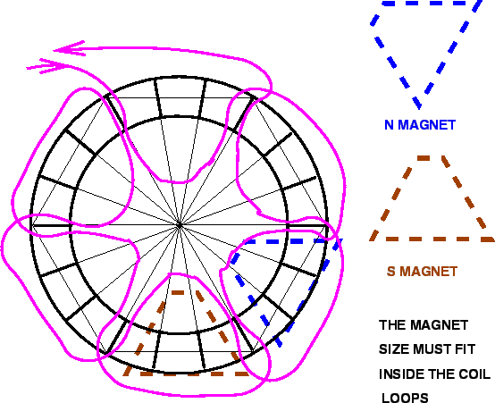
Figure 9.
The principle of the wave winding. The winding is shown for one phase, 6 magnets.
---
For a three phase, 6 magnet layout, the winding looks like in the next picture below.
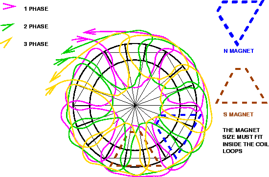
Figure 10.
Wave winding for three phase. Six magnets.
For each phase as many turns are needed as indicated by the voltage tests. To make the work easier you can use instead of one thick wire many thin wires in parallel.
- Hannu
