I threw together a bearing carrier today, rough & ready it was. Too rough & ready it turns out. The balance is terrible. But I got some data none-the-less.
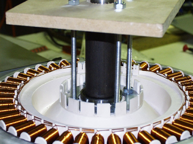
The first photo shows a close up of the clamp assembly. The problem lies in the piece of tube I used as a spacer between the two bearings. It's internal diameter is 27 mm, not 25 mm (which would fit snugly against the shaft). Also, the ends are hand finished, whereas they should be squared off in the lathe.

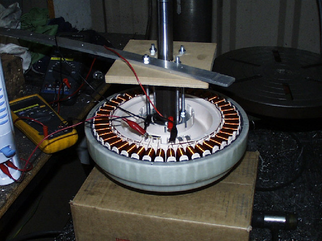
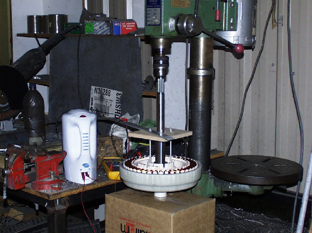
The next two photos show it sitting in the drill press, with a long aluminium bar used as a torque rod to stop the stationary bit turning. You can also see the two multimeters, and the jug I used as a dummy load.


The drill press is a somewhat dilapidated 1/2 hp unit. It's slowest speed is 280 rpm, which I used. One winding on the alternator, that is, from the neutral point to one free end, gave 79 volts open circuit. I measured the frequency at 137 Hz, which leads me to believe the true rotational speed of the drill press is 293 rpm.
I then connected the jug, full of water, as a load. The dc resistance of the jug element was 27 ohms. I then measured the voltage from the alternator at 49.5 volts, and the current at 1.8 amps. This equates to a power output of 89 watts.
It also gives me an internal impedance of (79 - 49.5) / 1.8 = 16 ohms. Now, since the DC resistance of that winding is 6.5 ohms, this warrants further investigation.
First, I don't think I have the rotor bedded all the way in to the stator. Second, my currents and voltages might be out of phase (this actually makes things even worse if that is the case); although I believe the jug element would be mostly resistive. Repeating the test with the dual trace cro will clarify this.
I've yet to extrapolate this data to determine the best way to hook up my transformers, but I think the further testing mentioned above should be performed first.
However. Extrapolating the data so far, to get 900 watts out of this unit, I need 511 rpm. My target is between 750 & 1000 watts peak. By the way, the limiting factor in getting power out of any alternator is internal heat. I believe the F&P unit scores particularly well on this point, being open to the air on side. It's also relatively large.
Using blade calc with the following data
Blades = 3
TSR = 6
Blade Efficiency = 0.4
Blade radius = 2.5 metres
Wind velocity = 6 m/s
gives 1034 watts at 137 rpm
trying some different numbers
Blades = 3
TSR = 6
Blade Efficiency = 0.4
Blade radius = 1.4 metres
Wind velocity = 9 m/s
gives 1095 watts at 368 rpm
The pattern is obvious. You need a small diameter blade & high wind to get the power at the required rpm's.
The upshot of this is you get progressively lower outputs at slower winds.
Whilst I still have much testing and number crunching to do, my feeling is that the way to maximise output from these units lies in a Savonius rotor (lots of torque) with a geared-up drive to the F&P alternator.
Another by the way. Doing a maximum power transfer analysis at 280 rpm, Vo/c = 79, Impedace = 16 ohms, all 3 coils, gives 292 watts. Pretty close to the quoted 300 watts output from one of these units rigged as a hawt.
I really need more data at higher rpm's to pursue this further. I expect the open circuit voltage to be linearly proportional to rpm, but what about the internal inpedance. If it's relatively constant, short of cooking the windings, the sky's the limit.
More later.
Amanda
PostScript......
Last minute thought. If I inverted the whole assembly in the drill press, the imbalance would be that much less. Might try it tomorrow.