Hello again everyone!
first i had problems in the second post as 8 or 9 of the photos did not make it into the post. kurt has left a message to see if the Dan's can insert the photos from their end. The urls that kurt left for the Dan's cannot be clicked on, but you can copy and paste if you wish to view them now. depending on outcome, i may have to repost #2. sorry for the inconvenience at this time.
this section will deal mainly with a rewind process to help you achieve a specific cut in voltage at your rpm needed, and will also allow you to pack in as much copper that will greatly increase the current carrying capability to its maximum. As i previously mentioned, in my opinion the best motor to search for is a 4 pole, 230/460 volt unit. totaly enclosed is best and open drip proof (open to atmosphere) is still very useable and will make an excellent unit. these style of motors and speed are very common. for now i suggest you keep away from 2 pole motors as they have very narrow diamater rotors in comparison to 4 pole units, but i will convert a few in the future to see what results i can get.
to further express my opinions for using induction motors, i will mention some of the points that make them very desirable. you have an excellent pre-engineered frame of either aluminum, cast iron, or rolled steel, and all have excellent heat disipating qualitys built into them which do an excellent job of getting rid of the heat when under a good load. the shafts are usually of a grade of steel which is stronger than regular cold rolled, trueness is less than .001 of an inch of runout, and supported by bearings which are capable of carrying heavy radial loads as well as a good amount of thrust. new bearings are relatively inexpensive and you can choose the sealed type which are greased for life, cutting back well on any needed maintenance of them. the laminations are of a few top grades of steel intended for the best transfer of flux and using the newer high eff motors have larger slots than the older motors which allow you to use even more wire in them.
there are many designs out there that people are building with very good results, and i give them an awful lot of credit for their efforts and information sharing. however i do believe that "pound for pound" induction conversions will give the most output and mechanical design cannot be beaten. (this is my opinion and am not challenging or looking for a debate on the issue)
ON WITH THE PROCESS.
So now we know that the first thing to do is build your rotor with the largest or what you can afford to use in neo magnets. you now have the option to use the existing winding or rewind for maximum performance. if you use the original winding or original winding with modifications and are happy with the results, that is great. if you do wish to rewind, you can base your conversion of the new winding on the results of the original winding, or use the one turn method as i do. either method works out the same in the long run as the formula is basically the same.
#1 make your rotor, assemble unit, belt drive or lathe drive in some fashion so that you can run at a specific rpm to gather some data.
#2 record your rpm (200 rpm or higher is best to get a good steady reading), take an ac volt reading between any 2 of the three output leads.
#3 if this is the original 9 lead Y connected motor, make sure you are either connected 1Y for 460 volt, or 2Y for 230 volt.
now you have the data required. connection, rpm, and volt reading.
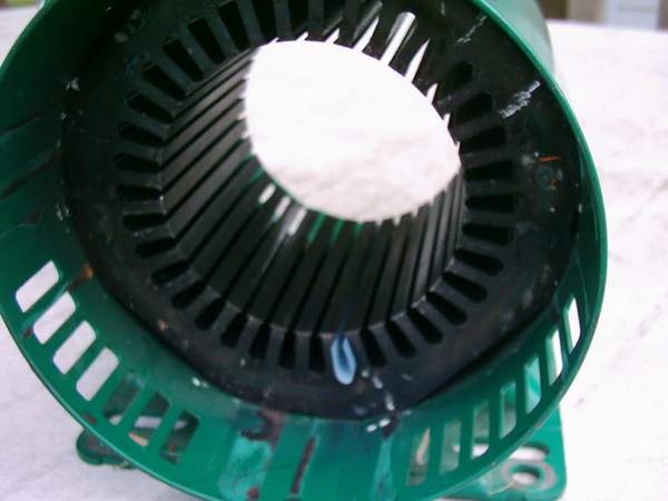
the next step is to strip the stator of wire and insulation. this can be accomplished by a few methods at home. cut off the opposite connection end as close to the laminations as possible. chemical strippers to remove varnish is a little dangerous without proper equipment. you can heat the stator to 300 degree faranheit in the oven which will soften the winding and help in the prying process to get the coils out, or you can be patient and tug and pull at a few of the wires at a time till you have it all out. be careful as possible not to damage the machined surfaces of the frame and laminations.
things to record while stripping:(assuming this is a 12-10-8 concentric winding)
#1 look at the motor lead wires and record how many magnet wire conductors are soldered to each lead. if more than one, use a micromater to see if they are the same size or not. record the size of each wire (with the enamel removed from the wire).
#2 assuming that this is a 12-10-8 concentric wound motor, you must now count the number of wires in each of the coils from the 3 different coil spans. if this is not of the 12-10-8 style winding, you will use the 1 turn method, but you should still count the number of wires in a coil slot. after you have counted the wires, divide them by the number of magnet wires soldered to the motor lead wire and record the guage of the wire. you now have the number of turns in each slot and you now know what is called the (SLOT FILL). SLOT FILL IS HOW MUCH TOTAL CIRCULAR MILLS OF COPPER THAT ARE CONTAINED IN THE STATOR SLOT. another note, if the turns were different in all 3 of the 12-10-8 spans, add all turns together from the three counts and divide by 3 to get the average per coil turns.
#3 you will now have to purchase new slot insulation and coil wedges. this material is available from any motor rewind shop. i suggest to use what is called "DMD" insulation which is a 3 ply material, dacron, mylar, dacron. the wedges are the same. ask for DMD 3-5-3 which is .011 of an inch thick.
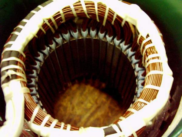
here is a pick of the 2 hp stripped stator with one piece of new insulation inserted.
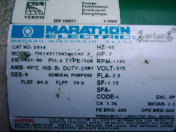
i will use the 2hp conversion that i have done for the examples. the 2 hp was originally a 575 volt motor. i stripped the stator and used the one turn method. if i had taken the readings with the original winding, the method would be the same, only with different input values, but i would have ended up with the same new data that i needed in the end.
My recorded readings of the test winding with 1 turn of #19 wire, 12-10-8 coil span, and connected for 1 Y.
@ 300 rpm-1.328 volt This is equal to ( 1.328 volt divided by 300 rpm )equals .0044266 volt per rpm @ 1 Y connection.
to get cut in voltage of 14 volt @200 rpm and 1Y connection i would need
turns= 14 divided by (.0044266x200 )= 15.81349 Turns per coil
i wish to use a 1 DELTA connection for this alternator for maximum current carrying capability and output. therefore i would convert my volt per rpm to Delta.
.0044266 divided by 1.73 equals .00256 volt per rpm for 1 DELTA connection.
formula for 14 volt @ 200 rpm and 1 DELTA connection
turns27.34375 Turns per coil
now i cannot make a coil with 27.34375 turns. so i round of to 28 turns. this will give me a cut in voltage of 14.336 volts, which is even a little better. the lathe test @300 rpm with the completed winding gave me a voltage of 21.75 volt, which would be 14.5 volt @200 rpm. SMACK ON!
choosing a wire size.
the original data of the 575 volt winding had 61 turns per coil with 2#23.5 wires on each lead. this gives you a slot fill of 55,388 circular mills (61x454x2). take 55,388 divided by 28 turns=1978.14 circular mills, or slightly more than 1#17. 1#17 is 2050 circular mills. the slot was able to accomodate the slight extra wire. the connection being 1 DELTA now has 2 #17 magnet wires attached to each of the 3 lead wires. lots of current carrying capability compared to the original 2#23.5 wires. this is the beauty of doing a complete winding conversion. almost forgot! the ohm reading of the original winding was 12.5 ohm, the ohm reading of the new winding is 1.1 ohm.
i did not bother to use more than 3 leads on the conversion, however i could have used 6 lead wires and made the connection 1Y-1Delta capable. the 1 Y connection would have given me a cut in voltage speed of 115.6 rpm, useful if you wish to make use of low wind speeds, and could be used with a Y-Delta contactor arrangment. but i guess i like things that run fast LOL!
Some of my thoughts.
i beleive most of you are capable of doing a complete rewind of this manner. most of you are already making coils for other project gennys and using and casting magnets in other fashions. if you are still shy about rewinding, use the existing winding, or make the rotor-get your data needed, and have a rewind shop do the rewind for you with your specs. you have already saved lots of money using the small mags to get an equal or better output compared to some other units, so that helps cover the cost of having it wound.
i am tending to like the faster running gennys before cut in voltage, this gives the prop more watts available before it actually has to start making watts. i also beleives this helps to eliminate stall of the prop. just some of my ideas that seem to be paying off and we can discuss it another time. also one other thing. when i first got involved i believed that the more poles in a winding was better, i no longer think that way and believe you can get just as good a performance from 4 poles as 12. its all in the design 
hope i haven't bored you with the long post, but many have requested that i do so in more detail. if you have any questions, please post it on the board and i will do my best to help if i can.
there are a few more pics at the end of the post of the 2hp unit i made, but will not be in service at my brothers until sometime in the late fall at the earliest.
having great fun as always and have truly enjoyed all the company and help from all of you people.
zubbly
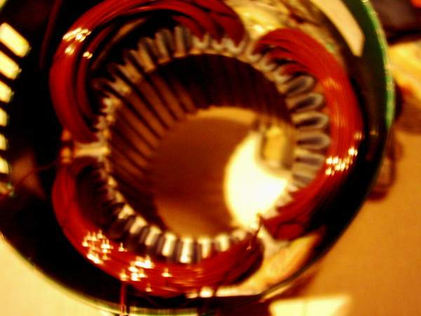
![]() "80%" src="http://www.otherpower.com/images/scimages/253/1_turn_test_winding_1.JPG">
"80%" src="http://www.otherpower.com/images/scimages/253/1_turn_test_winding_1.JPG">
pic of the one turn test winding

another view