This is an evolving design that I decided to try and come up with. I will update this as more components are finished.
Goals:
functional small mill for battery charging made from readily available parts
minimize cost
minimize fabrication time
maximize reliability
interchangable, reproducible components
Since the dual axle brake drum designs seem to work so well, I figured I would start by scaling that down to saw blade size rotors. Since schedule 40 pipe is readily available, I decided to build the frame of the genny from that.
Rotor: I have a stack of old 7 1/4" saw blades. I started by drilling 6 holes in a 2 1/8" circular pattern in a couple of blades. I have a bunch of 1" diameter 1/4" thick circular magnets. I arranged 16 of them on a blade leaving about a quarter inch between each magnet. If I can devise a decent design, I'll probably switch to Neodymium magnets as they would give much better performance.
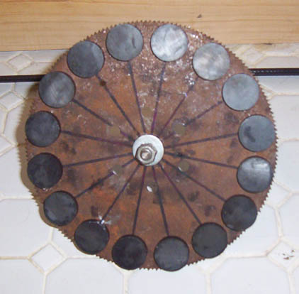
I didn't have a deck of cards, so I marked the magnet positions on the rotor with a protractor and compas.
Stator: I made a wedge shape as previous work was done by DANB and others arrive at and I didn't have the time to do that much research about the optimal coil at this point. I made a wedge of 1/2" plywood 1/2" at the bottom and 5/8" at the top. I wound a coil of 100 turns of about #30 or so magnet wire for testing. I mounted one of the rotors with magnets stuck, but not glued, onto a piece of 5/16" threaded rod and loaded that on my drill press which was set for 280 rpm. I only generated about a 3rd of a volt. Figuring that I needed to generate at least a volt or so per coil and that for a single phase machine. I wound a coil of 300 turns and generated about .91 volts with it. I wound up 16 coils of 300 turns each, made a stator mold out of some 1/2" ply wood and some spare boards, marked up the slots, greased the form, placed the coils, and cast the stator with 'Bondo' as it was the only polyester resin I had available at the time. I noticed when I removed the stator that some of the coils had shifted slightly, probably from
the thick bondo and the clamping of the mold, I'll order some polyester resin and hardner on line for future models. I tested the coils on the drill press and made the interconnections for a single phase stator. I was able to generate 20 - 21 volts from the stator. I expect it will perform better with the second magnet rotor. I wasn't able to measure the amps as that function on the meter I had with me was broken. Most of the time the wind speeds around here are slow so I will be looking for an early cut in speed.
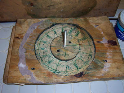
This was the mold for the stator.
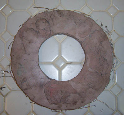
Here is an image of the stator at this point.
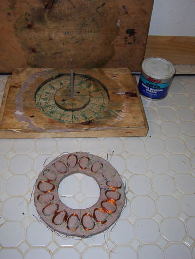
Another image of the stator and mold, showing the shifted coil positions. I think I need to glaze this side of the stator with a little more 'Bondo' to protect the coils.
