Hi all,
I had an odd idea a while back about trying a different style of rotor in an induction motor conversion.
So I decided to try it on this 1.5 hp motor that I already had some baseline numbers for with a 'normal' magnet conversion.
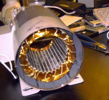
Here's a photo of the assembly - diassembled!
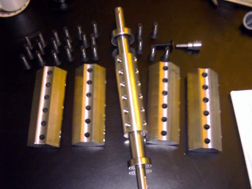
And another:
The shaft is made from 316 stainless (which is non magnetic). The four poles are mild steel.
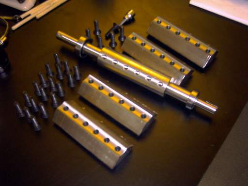
In the next pic one row of magnets is in. The slots where the magnets go were milled to .496 " which means the magnets have a 4 thou interference fit in the slots. When the bolts are torqued down, the four pole pieces act like collets and firmly squeeze the magnets in place.
The first row of magents goes in quite easily. But then the fun begins. To work properly each row of magnets has to oppose its neighbour. So the magnets want very badly to be anyplace but in the slot where they belong.
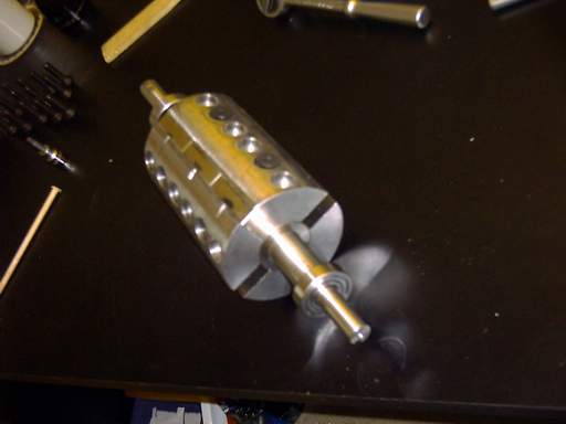
Eventually after a lot of cursing, a few large stainless hose clamps, various dowel rods, and a lot of magnets flying out here and there, all magnets are in place.
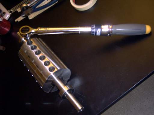
The 3/8 bolts get 30 ft lb on the torque wrench.
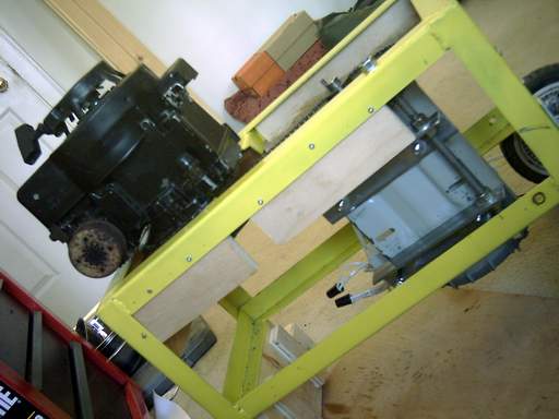
This is where this rotor is going:
And then the whole thing goes back on the test stand:
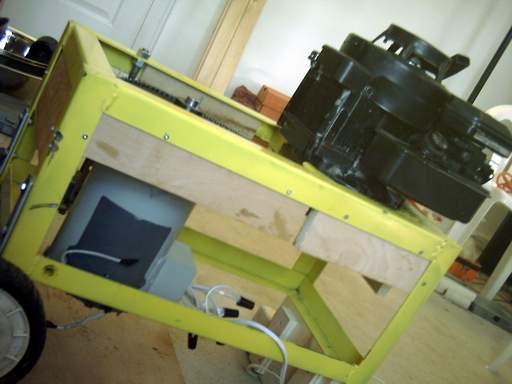
I ran another set of numbers for this setup, and saw an improvement over just putting the magnets on the rotor facing out.
In the previous test I got 21 hertz, 654 rpm, 600 watts, 110 VAC, 5.5 amps. With the same 600 watts worth of lights as a load, the new rotor gives 120 VAC at 575 rpm. That's about a 25% improvement.
Also with the new rotor there's 12 magnets as opposed to 16 on the old one.
Lots of fun in any case!
Ted.
