Author Topic: CNC wooden wind turbine blade project  (Read 11649 times)

0 Members and 1 Guest are viewing this topic.

richhagen

  • Hero Member
  • *****
  • Posts: 1597
  • Country: us
CNC wooden wind turbine blade project
« on: June 11, 2005, 07:28:35 AM »
I am posting this to update Ron and other interested parties on my wind turbine blade project.  The CNC mill is slowly progressing, Although I have a few bugs to work out with alignment, so for now I only have the small mill to work with.  As I am working my regular job and a couple of part time jobs right now, along with getting a bunch of apartments ready for re-leasing on 1 August, time has been, and for the short term will be an incredibly scarce comodity for me.  To take full advantage of the mill, I have been trying to program in visual basic, an application to generate the G-codes necessary to run the machine to generate a blade profile.  I started with a NACA 4415 profile for this project, as was suggested by Ron, (wdyasq), from here.  I found data for this profile in the University of Illinois at Urbana Champaigns on-line airfoil database.  This is a great resource to have available to us, and is located here:  


http://www.aae.uiuc.edu/m-selig/ads.html


My thanks go out to the University of Illinois for making this data available to us. I attended the Chicago Campus quite a few years ago for my undergraduate studies.


Next, one has to figure out what angles and dimensions the airfoil is to have at each incremental section of the blade.  To do this one has to have an equation that relates the ideal angle and chord width of the airfoil to the position out from the center of the blade radius.  This was pointed out to me by Ungrounded Lightning Rod when I made the small two foot diameter blades here:


http://www.fieldlines.com/story/2005/2/22/111119/599


To formulate the best approximate equations for the ideal angles and chord widths, I did a search on the web, and of course ran across a wealth of information posted by Hugh Piggot (scoraig wind), the father of the modern dual rotor axial designs built by so many of us here.  He has posted a wealth of information on the relationships of the chord and angles to the size of the rotor, the number of blades, and the position out from the center.  It took me quite a while to grasp most of the concepts he goes into, and I still have quite a bit of work to do there, but, having had a few fluid dynamics classes in the past, at least I was familiar with Reynolds numbers, and viscosity and such.  I have to get a copy of his book, I think I'll order one from DanB at Wondermagnet.com as soon as I finish this posting, as he has obviously put a lot of talent and thought into the concepts involved here.  I did find other information posted on line, but his was the most thorough I ran across.  There is an HTML version of some of his notes posted here:

http://users.aber.ac.uk/iri/WIND/TECH/WPcourse/page1.html

or the PDF version which Hugh has made available on his site here:

http://www.scoraigwind.com/wpNotes/index.htm

I used these approximations for the calculation of the ideal chord width and blade angle as I have yet to find a serious flaw with them or a better approximation.

I built a basic interface to enter the parameters:


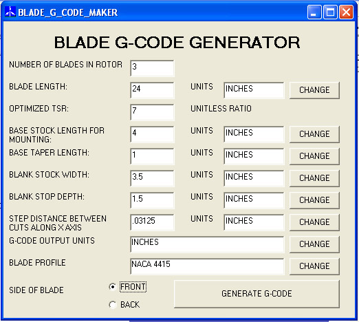
Interface to input blade parameters


To calculate the y and z coordinates for each position out along the x axis from the center the following steps are being programed:


First I calculate the ideal chord width and the blade angle.  

Next I convert the blade coordinates to polar coordinates

Then add the calculated ideal blade angle, and then convert back to rectangular coordinates.    

Then I calculate the minimum x and y values, because of the profile shape for the NACA 4415, these are always less than or equal to zero.

The profile is then shifted along the x axis so that the minimal value is zero.

This is repeated along the y axis, so that not the entire profile has x and y values that are all greater than or equal to zero.

Next a check is made to see if the maximum x and y values would fall outside of the material, and if this is the case, for right now, the size is scaled such that the maximum x and y values fall on the edge of the material.  (I still plan to, and have to change this so that the angle is adjusted in the case where the material is wider along the y axis to take full advantage of that width)

Once this is scaled you have the basic profile for that position along the x axis, or station. (this is as far as I have programmed, and as mentioned above, I still have a few modifications to work in)

Now, you have to do a little math on the profile to generate the x, y, and z positions for the g-codes.  If you are machining the front, then you have to machine to a depth of the negative of the z-value, and flip the profile around on the y axis from the basic profile provided by taking the width of the stock and subtracting the y value.  For the back side, the y-axis is OK, but you have to take the stock thickness and subtract off the value of the z coordinate from the profile to come up with the depth to machine to.  Then on top of this, this takes into account no tool offset, which would be fine for round nose bits, but I intend to use regular flat bottomed end mills, so I will have to compensate for that, which may involve some more complicated calculations, depending upon whether the next station is deeper, or more shallow than the last, and the diameter of the end mill.  I have some more thinking to do on that.  

For the base of the blade, I intend to taper the stock shape of the material into the first profile, and have included a variable to be entered which will indicate how steeply to do that.  basically, for each of those x-positions, it will generate the first profile, and then calculate the percentage of the depth equal to the percentage of the distance from the start of the taper to the first station.  I'm not sure how this will look, but we will see.

I also have to provide for the generation of the g-code syntax as this will generate the lines of text and add them to a text file for each x-position from the root of the blade serially out to the tip.


For now, I can generate the profiles only.  Here is an example of five stations exported to excell and ploted.  The series name represents the distance in inches from the center for a tsr=7 26" blade carved from a standard U.S. 2 by 4, the outline of which I added to the plot as a box.  


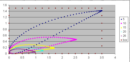
small sample blade stations for 26 inch tsr 7 blade 3 blade rotor from a 2 by 4

« Last Edit: June 11, 2005, 07:28:35 AM by (unknown) »
A Joule saved is a Joule made!

richhagen

  • Hero Member
  • *****
  • Posts: 1597
  • Country: us
Re: CNC wooden wind turbine blade project
« Reply #1 on: June 11, 2005, 01:37:26 AM »
The poll question should be referring to a dual rotor axial flux machine, I don't know why I keep calling them dual axle machines, I know better, but maybe the fact that It's Friday Night/Saturday Morning at 2:37AM local time has something to do with it.  Rich
« Last Edit: June 11, 2005, 01:37:26 AM by richhagen »
A Joule saved is a Joule made!

wdyasq

  • Hero Member
  • *****
  • Posts: 1324
Re: CNC wooden wind turbine blade project
« Reply #2 on: June 11, 2005, 06:47:50 AM »
Rich,


If I rrecommended the 4415 it was suggesting using a thicker blade for strength.  The Blade calculator JacquesM wrote used a 4412 and I think he could change airfoils.  Personally, after a lot of research, I am beginning to think one should use the s809 or similar airfoil.  


Another innovation we used was to put the Tip Speed Ratio and twist amount in slider boxes.  Using this method one can fit more 'twist' in a blank as nothing has to be normal in the blank for a CNC operation. Another observation I will make is the TSR should be considered but not be a design criteria, it should be the result of the criteria.  A small point but we are looking for design speed at wind speed.  TSR is the result.  It should not be on the front end of the equation if this is done with logic.


As mentioned, a flat bit was used for cutting.  I tend to use Her-Saf insert bits as the inserts are inexpensive and each has 4 edges. A flat bit will actually give a better surface at the same stepover as a ball-end bit on the flats and the same results at the edges.  A larger stepover will cut faster and leave a little more straightening and sanding on the leading edge for a lot less machine time.  It is not a bad trade-off, IMO.


I must qualify that I am not a programmer.  I have always drawn projects up and use CAM software to write the code.  The bit compensation and tool=path is figured in a 3D CAD program leaving only 'cut order' and jogs in the CAM protion of the programs. I have drawn up many of these little things and cut a few.  I am beginning to use larger diameter bits.  I am also using some stratigies of cutting twice, the first pass being a pass to rough and then a clean-up pass.


Well, enough rambling.


Ron

« Last Edit: June 11, 2005, 06:47:50 AM by wdyasq »
"I like the Honey, but kill the bees"

richhagen

  • Hero Member
  • *****
  • Posts: 1597
  • Country: us
Re: CNC wooden wind turbine blade project
« Reply #3 on: June 11, 2005, 11:11:04 AM »
I was thinking of setting it up so that the airfoil could be chosen from a variety which I would store in resource files such that the program would look up the selected profile data set.  I am not familiar with the s809, but I will look at it.  The first blades I made, I started out with a 4412, but then fattened it up so that it was probably closer to a 4415 anyway.


...'Another innovation we used was to put the Tip Speed Ratio and twist amount in slider boxes.  Using this method one can fit more 'twist' in a blank as nothing has to be normal in the blank for a CNC operation. Another observation I will make is the TSR should be considered but not be a design criteria, it should be the result of the criteria.  A small point but we are looking for design speed at wind speed.  TSR is the result.  It should not be on the front end of the equation if this is done with logic.'...


I'm not sure I understand this bit.  I figured that one would have an alternater that had a specific power output to rpm curve, and that the average winds would be a certain amount, with a specific extractable energy to wind speed curve, and that one would then choose the tip speed ratio to try to maximize the power out of the alternator under those conditions such that the power out of the alternator at that rpm was just under the extractable energy from the wind for that speed.  One would thus select the tip speed ratio in the blade design as a parameter for that rpm at that wind speed.


I saw that you centered the blade section in the blank whereas I have it in lower left as you look at it, but looking at the incremental airfoil sections I don't think this makes a functional difference in the blade.  I believe you guys did that so that you could symetrically taper the blank towards the tip and save material on the laminated blanks.


Since I am kind of writing this on the fly with no cam package, I will have to program the bit compensation.  I don't have any insert type of bits, but I think the programing would be the same as for a normal flat bottomed end mill, just adjust the bit diameter, which I will have to have as a parameter.  As for making the roughing and finishing passes, I will have to think about that, I had planned to add a check loop to ensure that I did not try to cut deeper than the flutes on the endmills, but other than that I hadn't planned for a finishing pass, that would require quite a bit more programing as I would have to set up another big loop to go from the tip to the root to finish it off.  I suspect I will try it with one pass from root to tip and see how it comes out first.  That is how I set up the smaller blades I made a while back.


Lastly thanks for the rambling as you have a lot more experience with this than I and I would like it to work as well as possible when it is done.  Thanks, Rich

« Last Edit: June 11, 2005, 11:11:04 AM by richhagen »
A Joule saved is a Joule made!

wdyasq

  • Hero Member
  • *****
  • Posts: 1324
Re: CNC wooden wind turbine blade project
« Reply #4 on: June 11, 2005, 04:32:14 PM »
and I would like it to work as well as possible when it is done...


As would we all....


You are correect in thinking we oriented the blade in the blank to optimise material.  I tend to look at things from conception out - and take a good look at the end product before I start to make pieces.  With the cost of good material, I believe it is stupid not to take a good look at materials and methods.  This should include everything from finishing cut to hold-downs and dust and chip handling.  Moving the blade in the blank allows for more blade to be made and still limit the 'Z' travel, a lighter blank and a less expensive blank.  


'I suspect I will try it with one pass from root to tip and see how it comes out first.'


Wood is a dynamic material.  Stresses put in wood by drying take YEARS to normalize.  My own choice of milling would be to mill one side rough, flip, mill other side rough, finish mill same side , flip - finish the first side.  I requires one more turn but allows stresss to be minimal in the final cutting.  Be sure and consider the jigs and fixtures wou will need to hold the material.


This stuff is all a 'guess' as far as I can tell.  I have never had a straight answer from anyone who claims to know anything except I am not doing right and whatever I am doing is not as good as it should be.


Victor had a good little note in a reply about the Hornet blades. I think he pegged it on design considerations.


What I 'think' is correct?

  Pick an airfoil with a wide range of accceptable angle of attack, especially at the root. Root AOA will vary far more than the tip.   If the tip-speed ration can be kept down, drag on blades will be lower, noise will be lower, Leading edge errosion will be minimized and other good things happen, IMO.


Basta,


Ron

« Last Edit: June 11, 2005, 04:32:14 PM by wdyasq »
"I like the Honey, but kill the bees"

rotornuts

  • Hero Member
  • *****
  • Posts: 537
Re: CNC wooden wind turbine blade project
« Reply #5 on: June 11, 2005, 11:45:51 PM »
wdyasq brings up a good point about stress release if you try to machine each side in a single pass. Not all pieces will create a problem but many may start to crook, twist or bow as you remove material. If you did a rough pass, flip, rough the other side, flip, finish, flip, finish final side you stand a far better chance of getting a uniform product. finding wood with eqaul growth ring spacing will help as well as there is less potential for stress accumulation or "tension wood" which characteristicly has closer growth rings. Unfortunately you usually need to see the end of the uncut log to identify these areas and are less likely to see it in a single piece. It doesn't hurt to look though.


Mike

« Last Edit: June 11, 2005, 11:45:51 PM by rotornuts »

richhagen

  • Hero Member
  • *****
  • Posts: 1597
  • Country: us
Re: CNC wooden wind turbine blade project
« Reply #6 on: June 13, 2005, 09:20:51 AM »
Hi mike,


I've been following your vertical mill with enthusiasm and I'm waiting to see someone post some power output from one.  I saw a post on one a guy made to charge a battery for his gate opener using a 30V Ametek once, but he used a boost converter to reach charging voltage.


After reading yours and Ron's comments on this, I am changing my planning for the big loops.  I will try to carve it in 4 passes as ron suggests.  I'm still on the KISS methodology though, so I'll probably use the same loops, just subtract a certain amount from the depth of the cut along the Z axis on the first passes for each side.  I like the logic from Ron of rough carving one side flipping, and carving the second side rough, then finishing the second side, flipping back and finishing the first as this appears to be the fewest interactions in order to use this methodology and carve the blade.  Rich Hagen

« Last Edit: June 13, 2005, 09:20:51 AM by richhagen »
A Joule saved is a Joule made!

rotornuts

  • Hero Member
  • *****
  • Posts: 537
Re: CNC wooden wind turbine blade project
« Reply #7 on: June 13, 2005, 10:42:44 AM »
I think you'll be happy with the results. 4 passes still qualifies in the kiss mantra I think. Kiss implies to me the fewest moves to make it right. I'm actually signed up to start the CNC machinist program at NAIT in august but well see. Maybe soon I'll actually understand what you guys are talking about.


Mike

« Last Edit: June 13, 2005, 10:42:44 AM by rotornuts »

mark72

  • Newbie
  • *
  • Posts: 1
Re: CNC wooden wind turbine blade project
« Reply #8 on: April 07, 2006, 02:36:50 PM »
Hi Rich,


I'm a new member here and I like the work you've done with the profile generator. Not totally sure how you input the profile shape to begin with though. Any chance you'll be sharing the program you've made with the group. Or I can offer a trade with you, if you supply the profiles I could draw up in 3D the blade using the profiles (a loft feature in Mechanical desktop). From there I can export 3D DXF or my preference is a STL (sterolithography file) that I then use with a program called Deskproto (quite simple to use ) to generate CNC code (demo available for free for 30 days).

I understand that you wish to generate G-codes directly yourself (which if you achieve it, is outstanding by the way), just offering another, possibly easier option.


  Mark.

« Last Edit: April 07, 2006, 02:36:50 PM by mark72 »