Following Zubbly's advice in my previous diary
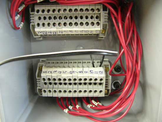
http://www.fieldlines.com/story/2005/7/18/174845/272 I was able to sort out the polarity of the 12 coil groups. When I had cut the connections to separate the 24 leads, I was able to use my multimeter to determine the 12 individual coil groups. As I had no idea on how to tell the polarity of the coils as I had originally connected them, some were cancelling each other out and I was getting nothing to measure. Zubbly suggested to take the rotor out and to get a DC power supply
and apply the positive to my odd number leads, and the negative to the even number leads.
Then with a compass I was able to check the polarity of each coil group,
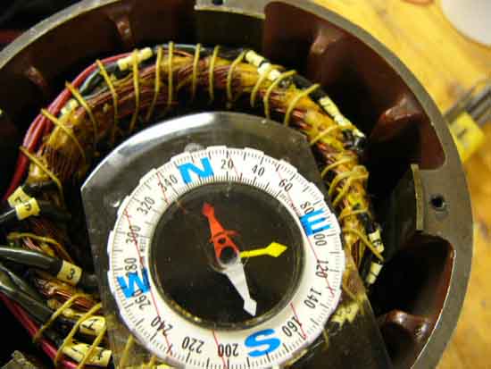
and decided to rewire the leads of the of the offending /cancelling coils so that the polarity of all the coil groups was North.
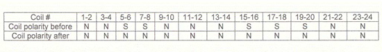
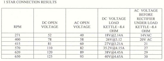
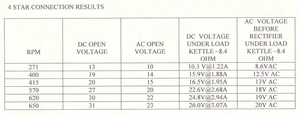
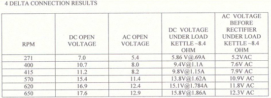
After all the polarities of the coil groups were verified the same I was able to apply Zubbly's wiring system and have the following results to share.
As a test load I used a kettle full of water 120V 1500W as a load (made by Black&Decker in Australia, for our friends down under:)). I measured the resistance of the kettle to be 8.4 Ohms. My wife still isn't aware of her contribution to windpower!
generator resistance 15.7 Ohms
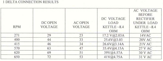
generator resistance 5.2 Ohms
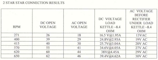
generator resistance 3.9 Ohms
generator resistance 1.3 Ohms
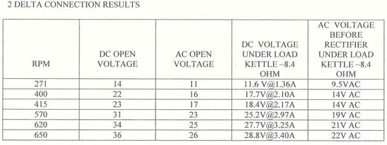
generator resistance 1.0 Ohms
kettle resistance 8.4 Ohm generator resistance .3 Ohms
I would love to hear feedback and interpretation of the data as to what would be the best connection to use, and as to a 12v or 24 volt system etc. Zubbly has had good results with a 3 blade 9 foot prop with a tsr of 6 or 7 a cut in of close to 200 rpm and I will soon start thinking about making my prop.
Thanks for reading and I hope you enjoyed, as always all comments welcomed.
Mike
