Author Topic: stator building specs, and pictures  (Read 9040 times)

0 Members and 1 Guest are viewing this topic.

picmacmillan

  • Hero Member
  • *****
  • Posts: 523
stator building specs, and pictures
« on: December 27, 2005, 04:11:55 PM »
Below is some notes and pictures of the stator making process the students went through to build their stator. It came out very well, and i think it is the best one so far. We began by making the stator mold.

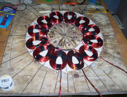
 The mold is 16" in diameter and was to hold 12 coils as described above. The center of the mold which is the most important part was made from 1/2" thick plywood as we dont want our stator to be too thick or we will lose a tremendous amount of power if the magnets couldnt get clost to one another if the stator was too thick.

 We wired it in star for 12 volts. The stator is 3 phase so to wire it, we took each phase(4 coils and soldered the end wire of the first coil to the start wire of the second, and so on til all 4 coils were soldered together.

  The start wire from the first coil and the end wire from the last were left for now. When we were done soldering all 3 of our phases up, we then took all the start wires and soldered them into a bunch, and all we were left with was 3 wires sticking out of the mold which each wires sticking out is 1 phase(hence 3 phase).


I like to encase all the wires in the fiberglass because i think it looks neater with no wires exposed, and the wires cant get scratched or broken once they are hardened in the stator. The only bad thing that i can see here is that you cant change your stator later from star to delta(read some good posts on fieldlines to learn what star and delta wiring is).


 We then put the fiberglass resin into the mold and put the lid on. I like to use a sander and vibrate the top of the mold for a bit to release any air bubbles and to get the stator nice and flat. You could lightly tap it with a hammer too and the desired effect would take place also.


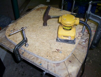
some say to wait 2 hours to take the lid off the stator but i wait until the next day and as pictured here, it came out excellently. We use grease on the top and bottom of the mold so it will release easily.


src="http://www.otherpower.com/images/scimages/1135/lid_off_stator.jpg" width=80%>


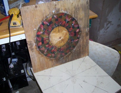
above is the picture of the bottom off the stator and all that is left is the 1/2" thick plywood holding the stator in and ensures the stator is 1/2" thick which is perfect. I found that because i screw the stators 3 pieces together, top, middle and bottom, that it would be advantageous to put some grease or soap into the heads of the screws so that hardened fiberglass that may be excess, doesnt get into the screw heads and you then have to do more work to clean the fiberglass out of them to release the stator from the mold.


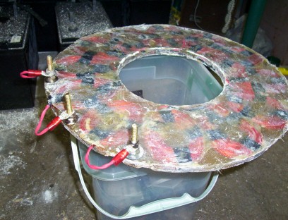
Finally below is a picture of the stator completely out of the mold. I use a dremel tool to carefully cut the stator from the mold, Be extra carefull in this stage as you dont want to knick the wires in or around the stator, or else you have bigger trouble. I have done this before, thats how i know. Once the wire is cut, you have to remove some hardened fiberglass to solder an extension on the stator wire. It could be worse also and your stator is garbage. Please be carefull here.The last thing we did, was to add 3 brass bolts on the stator so it will be easy to connect the wires to the wire going down the tower. The bolts are bought at any plumbing store. I believe they are the long bolts that hold the back of your toilet to the business end of you toilet :) lol  


Well,that was it for that day. The next day we will start on the blades. Dan tells me that i can use 12' blades on this turbine so that is way better than the 10' ones i was going to use, and because blade windswept diameter is one of the primary reasons for more power, this genny will produce alot more power than we initially hoped for... :) pickster

« Last Edit: December 27, 2005, 04:11:55 PM by (unknown) »

Shadow

  • Sr. Member
  • ****
  • Posts: 473
Re: stator building specs, and pictures
« Reply #1 on: December 27, 2005, 10:59:20 AM »
Looking good so far! On mine I soldered the wires to the brass bolts before putting it in the mould. Then drill three holes through the mould for the bolts to protrude. That way you have no wires coming out of the stator, everything is total enclosed.
« Last Edit: December 27, 2005, 10:59:20 AM by Shadow »

picmacmillan

  • Hero Member
  • *****
  • Posts: 523
Re: stator building specs, and pictures
« Reply #2 on: December 27, 2005, 11:39:10 AM »
hi shadow, :) i will try that on my next one, a good idea thanks for the tip .....  pickster

« Last Edit: December 27, 2005, 11:39:10 AM by picmacmillan »

willib

  • SuperHero Member
  • ******
  • Posts: 2414
  • Country: us
Re: stator building specs, and pictures
« Reply #3 on: December 27, 2005, 08:02:06 PM »
Looks great , really !

what is the resistance/phase of the two strands of #14 wire?
« Last Edit: December 27, 2005, 08:02:06 PM by willib »
Carpe Ventum (Seize the Wind)

dinges

  • Hero Member
  • *****
  • Posts: 1294
  • Country: nl
Re: stator building specs, and pictures
« Reply #4 on: December 27, 2005, 08:06:35 PM »
Good idea of the sander! Will have to remember that for the next genny.


All looks very nice, BTW.


Peter,

The Netherlands.

« Last Edit: December 27, 2005, 08:06:35 PM by dinges »
“Research is what I'm doing when I don't know what I'm doing.” (W. von Braun)

dinges

  • Hero Member
  • *****
  • Posts: 1294
  • Country: nl
Re: stator building specs, and pictures
« Reply #5 on: December 27, 2005, 08:10:17 PM »
I forgot;


you could just incorporate six 'electrical' bolts into the stator, instead of the three you have now. That way you can externally wire or switch from star to delta. It's how I build my stators, gives me the extra option for 'finetuning' and future experiments with automatic switchover from star to delta.


Basically, all you do is make both the start and end of each separate phase accessible to the outside. Adds a bit of flexibility to the design.


Peter,

The Netherlands.

« Last Edit: December 27, 2005, 08:10:17 PM by dinges »
“Research is what I'm doing when I don't know what I'm doing.” (W. von Braun)

picmacmillan

  • Hero Member
  • *****
  • Posts: 523
Re: stator building specs, and pictures
« Reply #6 on: December 28, 2005, 11:24:59 AM »
shadow? do you have apicture of this, or explain it al little better, i cant visualize what you did/? sounds like a good idea? does the bolt get fiberglassed also? or do you leave the bolt hanging out and then drill the mould?? not sure
« Last Edit: December 28, 2005, 11:24:59 AM by picmacmillan »

picmacmillan

  • Hero Member
  • *****
  • Posts: 523
Re: stator building specs, and pictures
« Reply #7 on: December 28, 2005, 11:33:59 AM »
4 coils of #14 wire(2 strands in each coil) was .4 ohms


« Last Edit: December 28, 2005, 11:33:59 AM by picmacmillan »

dinges

  • Hero Member
  • *****
  • Posts: 1294
  • Country: nl
Re: stator building specs, and pictures
« Reply #8 on: December 28, 2005, 12:32:54 PM »
Did you try measuring resistance of the meter wires alone?


I'm pretty sure it'll be about .2-.3 ohm (or in any case, not negligeable); with my meter & wires it's .4ohm. These are high quality mil-spec measurement probes (the DMM is a different matter; now I think of it, the probes have cost more than the meter...)


There are other ways to accurately measure these low resistances (see some previous posts on the subject).


Peter,

The Netherlands.

« Last Edit: December 28, 2005, 12:32:54 PM by dinges »
“Research is what I'm doing when I don't know what I'm doing.” (W. von Braun)

picmacmillan

  • Hero Member
  • *****
  • Posts: 523
Re: stator building specs, and pictures
« Reply #9 on: December 28, 2005, 02:34:19 PM »
naw dinges i didnt measure the wires alone..just put it on the meter and read it from there...the resistance for these is like said above, almost negligable, from past practice i know the amount of turns coupled with the wire size really works well for the size of machine we are building.... i know everyone does it a little differently, but i have had success with this so i dont mess with it..i suppose i could tweak it and get a bit more power here or there, but i suspect i could also do harm ...so i just leave it alone...pickster
« Last Edit: December 28, 2005, 02:34:19 PM by picmacmillan »

Shadow

  • Sr. Member
  • ****
  • Posts: 473
Re: stator building specs, and pictures
« Reply #10 on: December 28, 2005, 03:18:30 PM »
Hey Pic, Hopefully these pictures come through, after I had all the coils wired together and soldered then I cleaned the enamel off about an inch or so and wrapped it around the 'toilet' bolt and soldered it

you may want to cut the bolts off shorter, I cut mine later. The toilet bolts have a nice flat base so stand up by themselves.

make sure they are spaced so as not to touch each other. Then I drilled holes for them to stick out the stator mould, I greased the holes a bit with vaseline for easy removal. In fact I used it all around the mould.

I kinda overfilled my mould anyway so had a little seep out around the bolts but very little. I put some resin in the bottom, then the fibreglass donut piece then slid the stator and bolts in then filled with resin and one more donut ring of cloth on top. And like you I waited 24 hours.This way now everything is totally enclosed in resin. Hope this helps
« Last Edit: December 28, 2005, 03:18:30 PM by Shadow »

theTinker

  • Full Member
  • ***
  • Posts: 104
Re: stator building specs, and pictures
« Reply #11 on: December 28, 2005, 03:30:22 PM »
ive yet to get to that stage myself but dinges that is one of the most simpliest and useful ideas ive ever heard. good thinking
« Last Edit: December 28, 2005, 03:30:22 PM by theTinker »

dinges

  • Hero Member
  • *****
  • Posts: 1294
  • Country: nl
Re: stator building specs, and pictures
« Reply #12 on: December 28, 2005, 10:14:59 PM »
I'm not sure if you understood me or I you.


What I meant is that the DMM+wires have a resistance of their own, which adds up to the resistance of the coils you're measuring. It's ok to measure all 4 coils in series, but your DMM may introduce an error.


I say it because my DMM has a resistance of about .3-.4 ohms when I short the wires. If yours doesn't, so much the better, but it will be at least .1ohm, I expect.


For measuring low resistances (<20 ohm, <2ohm, and <0.2ohm; resolution .1 milliohm) I have built a small piece of equipment (current source of 1A with a built in millivoltmeter). With this, I can measure very small resistances; like those of a screwdriver (18.8mohm) or cable shoes connected to welding wires (.005-0.006 ohms). Comparing various measurements of this with my DMM has shown me how inaccurate DMMs (at least mine) are in the <1ohm range. When I built this meter, I thought I'd use it only a few times in my entire life; now I have it, I use it about once a week... Reassuring to be able to verify the exact resistance of a connection, a switch or a relay.


Good luck with the rest of your genny! Looking forward to rest of your experiences (prop, pivot, mast, etc.)


Peter,

The Netherlands.

« Last Edit: December 28, 2005, 10:14:59 PM by dinges »
“Research is what I'm doing when I don't know what I'm doing.” (W. von Braun)

elvin1949

  • Hero Member
  • *****
  • Posts: 645
Re: stator building specs, and pictures
« Reply #13 on: December 29, 2005, 04:58:58 AM »
Shadow

 Pure genius and simple.

Thanks for the tip.

later

Elvin
« Last Edit: December 29, 2005, 04:58:58 AM by elvin1949 »

picmacmillan

  • Hero Member
  • *****
  • Posts: 523
Re: stator building specs, and pictures
« Reply #14 on: December 29, 2005, 06:39:15 AM »
i would have to say that youre coils are the nicest ive seen :) good job ..pickster
« Last Edit: December 29, 2005, 06:39:15 AM by picmacmillan »

picmacmillan

  • Hero Member
  • *****
  • Posts: 523
Re: stator building specs, and pictures
« Reply #15 on: December 29, 2005, 06:41:51 AM »
fantastic idea dinges..where were you when i screwed up my first few stators :) have a good one ..pickster
« Last Edit: December 29, 2005, 06:41:51 AM by picmacmillan »

BruceDownunder

  • Full Member
  • ***
  • Posts: 159
  • Country: au
Re: stator building specs, and pictures
« Reply #16 on: December 29, 2005, 01:10:04 PM »
Hello Peter, I'd be happy to look at your set-up of how you made the extra low resistance meter-a few pic's and a Cct. - I've wanted to build one  recently .

Thanks

Bruce
« Last Edit: December 29, 2005, 01:10:04 PM by BruceDownunder »

willib

  • SuperHero Member
  • ******
  • Posts: 2414
  • Country: us
Re: stator building specs, and pictures
« Reply #17 on: December 30, 2005, 09:44:29 PM »
Hi pic, i  also think that the resistance is less than 0.4 ohms .

usually you have to subtract the 'rest state reading' from the reading on the meter ..

mine is usually around .9 ohms ( touching the probes together)so if i get a reading of 1.0 ohms then i know that what i am actually reading is .1 ohms..
« Last Edit: December 30, 2005, 09:44:29 PM by willib »
Carpe Ventum (Seize the Wind)

dinges

  • Hero Member
  • *****
  • Posts: 1294
  • Country: nl
Re: stator building specs, and pictures
« Reply #18 on: December 30, 2005, 09:55:56 PM »
Bruce,


I'll scan the schematic (hand drawn for my own purpose, but understandable) ASAP and will post it here, along with some notes and pictures of the outside & inside of the project.


Thanks for the interest,


Peter,

The Netherlands.

« Last Edit: December 30, 2005, 09:55:56 PM by dinges »
“Research is what I'm doing when I don't know what I'm doing.” (W. von Braun)

dinges

  • Hero Member
  • *****
  • Posts: 1294
  • Country: nl
Re: stator building specs, and pictures
« Reply #19 on: December 31, 2005, 11:13:56 PM »
Bruce,


check out this new thread on my milli-ohm meter. Should contain all the info you may need:


http://www.fieldlines.com/story/2005/12/31/125745/30


If you've any more questions, let me know.


Peter,

The Netherlands.

« Last Edit: December 31, 2005, 11:13:56 PM by dinges »
“Research is what I'm doing when I don't know what I'm doing.” (W. von Braun)