Author Topic: Big, unconventional blades  (Read 2946 times)

0 Members and 1 Guest are viewing this topic.

hvirtane

  • Hero Member
  • *****
  • Posts: 712
    • About Solar Cooking
Big, unconventional blades
« on: December 29, 2005, 08:53:19 PM »
Last year (2004) I helped my friend Erkki Nousiainen to make a new wind rotor for his old wind machine.


The machine has got an induction generator with

a gearbox. The wind rotor diameter has been originally 10 m, it had two FRP blades. There has been a pitch control mechanism.


Last year (2004) we started to make a new wind rotor of wood for it, 10 m diameter.


'Eki' discharged the pitch control mechanism, which he said never worked really properly. I made for him a new design for the blades.


The design of the rotor blades was based on an idea of a wind machine builder called 'Reinikainen', who made some big wind machines in the nearby area earlier. The blades are made of wooden boards.


Here is a picture of an original 'Reinikainen machine', which is still working after about 15 years in use.


The blades are made by laying wooden boards on the top of each others like a fan and then using tools.


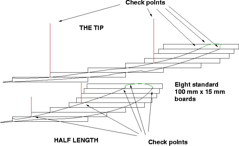
My plan was to use on the tips the K2 airfoil.


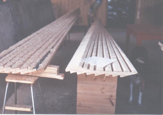
Here is a picture how the blades were made in 'Eki's workshop.


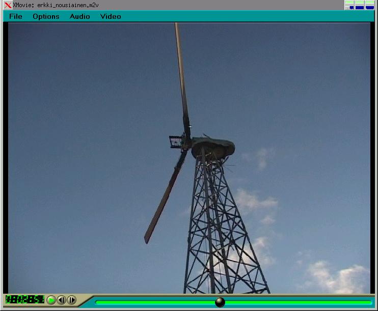
Here the blades are installed on the wind machine, of 'Eki'.

There is no pitch control mechanism used, but some working parts like the counterweights were left there...


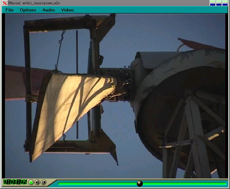
Here is a shot of the blade tip.


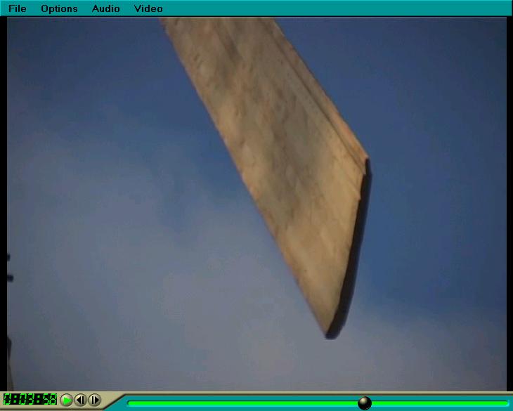
Another shot of the tip of a blade showing clearly the K2 airfoil.


The last three pictures are taken from a video tape as made by 'Ossi'. We are working with the video, there is lots of other information about 'Eki's other machinery there.


---


Unfortunately 'Eki' didn't manage to get the induction generator working. He left the machine turning free during a stormy night in the winter 2004. At that time I was in India. I heard next day by email that the wind rotor was broken.


In my opinion the wind rotor was really successful. It was going quite fast, at least when going 'free'. 60 RPM was quite easy to achieve.


It was broken because of the too fast speed and mainly because the old weights of the discharged pitch control mechanism went loose and started banging 'out and in'.


---


Now a new wind rotor consisting of eight blades is almost ready and 'Eki' has tested the generator so that it will work at this time. During the next week we are planning to lift the machine again up...


- Hannu

« Last Edit: December 29, 2005, 08:53:19 PM by (unknown) »

Waterfront

  • Jr. Member
  • **
  • Posts: 60
Re: Big, unconventional blades
« Reply #1 on: December 30, 2005, 05:34:49 AM »
Wow, Big is right! hehe


It's the first time I see blades being made that way, the finished product looked really good, it's too bad they broke... So what's the power output of the alternator with monster blades like that??


Keep on posting!

« Last Edit: December 30, 2005, 05:34:49 AM by Waterfront »

hvirtane

  • Hero Member
  • *****
  • Posts: 712
    • About Solar Cooking
Re: Big, unconventional blades
« Reply #2 on: December 30, 2005, 07:46:46 AM »
The old generation gu(r)ys here made their machines quite big. The main idea was to get some heating power out the machines. I've heard from another guy that this particular machine was earlier powering electric Sauna heating elements, before 'Eki' bought it. The power of the generator is 15 kW. As far as I know the original FRP blades were working some time quite well. But the blades were broken, when 'Eki' took the machine to the place, where it is now.


Concerning these new, now broken blades.

With my friends I've been experimenting with quite similar blades a bit more. Another friend of mine made a four blade wind rotor of 3,5 m using similar methods. That rotor didn't have any real airfoil shape, but anyway it worked very well. It is a direct drive axial flux PMG machine. It is not in use now, because the tower is used to hold up another a bit bigger machine.


I had quite much email correspondence with an Australian guy, who started to make similar looking blades, in Fiji.


I tried to convince 'Eki' to make a new set of two very similar blades as shown in the pictures. But now he has got almost ready a new wind rotor of 8,5 m with eight blades. The blades look quite similar as the blades of that 'Reinikainen' machine. I will post here on this board some pictures later.


- Hannu

« Last Edit: December 30, 2005, 07:46:46 AM by hvirtane »

hvirtane

  • Hero Member
  • *****
  • Posts: 712
    • About Solar Cooking
Re: Big, unconventional blades
« Reply #3 on: January 08, 2006, 06:28:31 AM »
'Eki' lifted the new rotor up yesterday.

The rotor construction is something

quite similar as with the 'Reinikainen'

machine. But the shape of the blades

is quite much like the K2 airfoil.


Waiting for the wind.


- Hannu

« Last Edit: January 08, 2006, 06:28:31 AM by hvirtane »

domwild

  • Sr. Member
  • ****
  • Posts: 357
Re: Big, unconventional blades
« Reply #4 on: January 16, 2006, 11:20:05 PM »
Great pictures! Is this a wooden tower? Looks like it.


Interesting method of blade construction. They may not be aerodynamically perfect, but, what the heck, they work.


*

« Last Edit: January 16, 2006, 11:20:05 PM by domwild »

hvirtane

  • Hero Member
  • *****
  • Posts: 712
    • About Solar Cooking
Re: Big, unconventional blades
« Reply #5 on: January 17, 2006, 06:07:49 AM »
The tower is made of angle iron.


We are little by little developing

this blade making design.


I've actually never much believed

the idea that the blades

should be narrow at the tips.

The calculation to achieve

narrow blade tips is based

on the assumption that the torque of

the blade should be the same at

all places of the blade.

If your blades are strong enough,

you can make them wide at the tips.


You can quite easily make the angles

and the airfoil shapes

of the blades correct with this method.  


Now the machine is up and working.

We have got a problem, which I was

expecting. When there are now

eight blades the speed of the wind

rotor is so much slower

(than in the original layout) that

the generator reaches the working operation

speed a bit too late. The induction generator

was originally matched with the wind rotor of

two blades.


- Hannu

« Last Edit: January 17, 2006, 06:07:49 AM by hvirtane »

IntegEner

  • Full Member
  • ***
  • Posts: 159
Re: Big, unconventional blades
« Reply #6 on: January 17, 2006, 07:43:18 AM »
Excellent work proudly displayed. Blade tips and the outer lengths of the blades are where most of the energy is gained. It is important to note, however, that the theorizing always gives the small friction drag of the blades little thought. I fully concur that wide blade chords out to the tips and more blades are helpful in general but means must be found, such as with thin and gently cambered profiles, to maintain ultra low drag. Wind energy can only benefit from more discussion about this!


(As a possible topic, thinner blades placed one behind the other some distance and supporting each other front and back with a few metal braces instead of all in a circle on the rotor. The idea is to deflect the wind and doubled blades like this can work with perhaps less blade thickness. We here would be interested in obtaining such a rotor of up to a 3 meter diameter for mounting on our 4.5 meter tall wooden tower for tests.)


Anthony C.

www.integener.com

« Last Edit: January 17, 2006, 07:43:18 AM by IntegEner »

finnsawyer

  • Hero Member
  • *****
  • Posts: 1565
Re: Big, unconventional blades
« Reply #7 on: January 17, 2006, 09:45:45 AM »
Be careful about using the word "always".  Not everyone ignores drag when considering blade design, as the two go together like, well, "a horse and carriage".  ("You can't have one without the other").  I recently outlined a methodology for incorporating both drag and lift in blade design.  Here it is:


The TSR is a design parameter for the blade.  Once determined, the velocity of any point along the blade is a fraction of this.  For instance, if the TSR is 8, the magnitude (different directions) of the tip velocity is eight times that of the wind, while at half the radius the magnitude of the blade velocity is half that, and so on.  Once you know the magnitude and direction of the blade velocity at any point along the blade you can calculate the effective wind velocity seen by the blade at that point by using vector algebra.  Once you know the effective wind velocity you are in a position to determine the pitch angle or twist of the blade.  To do this correctly you need to use the lift coefficients and drag coefficients for the air foil which makes up the blade to determine the force acting on the blade at the given point.  Since the forces on the blade are constant, the power generated by a small length of the blade at radius r is equal to the magnitude of the force per unit length on the section acting in the direction of rotation times its speed times its length (actually the dot product of the vector force acting on the section and the vector velocity of the section).  This in turn is set equal to the available power (remember to consider Betz's limit) provided by the wind in a ring or annulus of radius r and width equal to the length of the blade section.  From this you determine the pitch angle of the blade at radius r.  Note that different blade widths will yield different values for the pitch angle.  In general this is done for the total blade width obtained by adding up all the blade widths for that value of r.  The fact that the lift coefficient and drag coefficient are well behaved over about a twelve degree range means that you can have blades that are constant in width, or taper toward the tip, or even get wider toward toward the tip as long as each point of the blade is within this 12 degree range.  Of course wider blades will have more drag losses than narrower ones.


So you see drag is not always ignored.  In fact, because of the peculiar geometry of the wind - windmill interaction, its effects become quite important.  Note that this approach gives the total width of the blades for each value of radius, which one expects may be divided into as many blades as one wishes without any loss of efficiency as long as everything is scaled accordingly.


To use your 'thin' blades in effective designs it is necessary for you to actually determine their lift and drag properties.  While you could build actual windmills it is likely that doing wind tunnel tests before hand would be productive.


« Last Edit: January 17, 2006, 09:45:45 AM by finnsawyer »

IntegEner

  • Full Member
  • ***
  • Posts: 159
Re: Big, unconventional blades
« Reply #8 on: January 19, 2006, 08:03:55 AM »
The intent seems sincere and honorable here but it misinterprets a few things and in general, without being disrespectful (forgive me if I am), I believe that, in the hurry to just type in a lot of words to keep an oar in the water, not much light is being shed.


Anthony C.

www.integener.com

« Last Edit: January 19, 2006, 08:03:55 AM by IntegEner »

finnsawyer

  • Hero Member
  • *****
  • Posts: 1565
Re: Big, unconventional blades
« Reply #9 on: January 19, 2006, 09:56:31 AM »
Which part of the explanation didn't you understand?  My interest is in HAWTs, yours apparently in VAWTs.  Perhaps that accounts for your confusion.  The technique is designed for high TSR HAWTs.  As far as keeping an oar in the water, you have been all over the lake and have provided one very suspect equation and one very useless set of computer generated curves for all the splashing and churning.  Recently you stated your intention to seek funding to eliminate the shortcomings of wind mill blades by adding additional blades above and behind them. Of course, such blades will add their own shortcomings such as more drag and disturbances in the air flow.  In fact, these new blades may have the same shortcomings as the old blades.  Well, then add some more.  Nothing like complicating matters.  Above all, have fun.


One thing more.  It appears that your reason for adding the extra blades is to cause the air flow over the original blades to be laminar.  Well, if memory serves me right, I believe that in wind tunnel tests involving model air foils it was found that the air flow was laminar, whereas in larger air plane wings it is laminar only over the leading few inches.  You may, in fact, be trying to solve a non existent problem when it comes to windmill blades.  

« Last Edit: January 19, 2006, 09:56:31 AM by finnsawyer »