Author Topic: The Design Phase  (Read 2075 times)

0 Members and 1 Guest are viewing this topic.

SamoaPower

  • Sr. Member
  • ****
  • Posts: 417
The Design Phase
« on: February 05, 2006, 04:44:22 AM »
I want (need?) a wind generator.


Actually, I already have three but they're small.


Okay, where do I start? It seems looking at this site, which I've found most valuable, that there are a few possible starting points. The air rotor (I still like the word rotor, but you may prefer blades),  the alternator, the system or needs? The optimum choice may depend on what you have to start with. In my case, it seemed most logical to start with what my location has to offer. Fortunately, NOAA has a monitoring site not far away. I understand that there are similar resources for many areas.


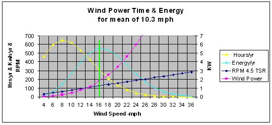
NOAA determined that our mean annual wind speed, a six-year average, is 10.3 mph. Not great wind, but enough to work with. Calculating the Rayleigh time distribution of wind speed for this mean produced some surprises. For example, I should have winds of 8 mph for more of the time, during a year, than any other speed. Interesting. Initially, I thought this meant that I needed a generator that was optimized for this speed. Wrong! I forgot about the V^3 power factor. Calculating the energy distribution for this time distribution shows that my maximum energy peak is at 16 mph. Ah, that sounds better, but this is still far off from the commercial machines that produce rated power at 25 mph or more. Obviously, I need to roll my own.


Another factor that impacts my starting point is that I already have some components I would like to use if I can. I have a set of blades (actually two sets of three blades) that are designed for 42% efficiency at a TSR of 4.5. It's hard to do much better than that. These are constructed of a tubular aluminum spar and formed aluminum skin over ribs using a high L/D (100), under-cambered airfoil (Wortmann FX 60-126). The blades have a constant 13" chord with no twist. The swept area is 201 ft^2, which is 16 ft diameter. I also have a variable pitch hub for these blades for which I intend to use active pitch control. I can already hear the groans in response to using aluminum and variable pitch. The consensus on this site seems to be that aluminum will fail from metal fatigue and variable pitch is too complicated to be practical. I have to wonder if these are the real reasons that they're rejected. In any case, we shall see. This will be a down-wind machine hence, no tail feathers.


Here's a chart showing the Rayleigh time distribution, the energy distribution, the available power from my air rotor and its RPM vs. wind speed.


Now we come to need. Most are going to say, "as much as I can get!"  Sure, I feel the same way but also understand there's a practical limit. First, I want to stay with a 12 volt system. Why? Most of my off-grid loads, by far, are 12 V. I have no 24 or 48 volt loads and my two 12 volt inverters will handle the AC loads just fine. Yes, I understand that the higher current will incur more losses but I have a few techniques in mind to combat that.  You see, I don't mind complexity. In fact, I welcome it - it offsets boredom. The KISS principle certainly has merit, but what do I have to give up to get it? I don't live off the grid so I don't have to depend on RE. Then, why do I do it at all? Simple - it's fun! Maybe someday I'll save a few bucks (problematical), but if I don't, I can still say I've enjoyed myself. However, with increasing energy costs, it may pay off sooner than expected. Our grid rates are now up to 26 cents/kWh. The number I picked out of the air (ha!) for the wind generator is 1 kW at 12 V at 16 mph wind speed - a low speed machine.


Okay, so what's next? Guess I better take a look at the alternator. The axial flux machine was unfamiliar to me before coming to this site. What a neat idea! It looks like it should be ideally suited for what I want - simple, low speed capable and good output - until I saw efficiency numbers of 50% being bantered about. I've got this thing about efficiency - small numbers don't get my attention. So, what's the deal? Is 50% all I can look forward to? After digging out the formulas and cranking them through a spreadsheet, I see that it can do better than that. It's the usual problem of trying to match up the components of a system - it takes a systems viewpoint. One thing I decided early on is that I'm not very much concerned about winds over 24 mph - they simply don't occur very often here. Also, a variable pitch air rotor can cure a lot of ills that fixed pitch can't cope with.


The variable pitch hub has a back plate of ¼" mild steel - looks like I can use it as one magnet rotor of a dual rotor alternator. It's 18" in diameter and heavily reinforced so distortion should not be a problem. Looking at the most bang-for-the-buck deal on magnets quickly showed that the 2x1x.5 magnets had it. At four bucks each for N40s from eBay, they have the advantage compared on unit volume. Unfortunately, a single magnet, of this size, per pole, isn't going to be enough. However, two in line radially, giving 4x1x.5 looks reasonable on an 18" disk with enough magnet to get the power in the RPM range (55 to 189) available. 16 poles will fit with reasonable spacing and requires a total of 64 of the 2x1x.5 magnets for the two rotors. This, of course, means 12 coils for 3-phase.


The numbers say that I need 32 turns for cut-in (13Vdc) at 7 mph (55 RPM, star (wye) connected) and a graphical analysis says that I can fit 3-in-hand #14 AWG (#9 equiv.) into the available space that yields 27 milliohms resistance per coil. Coils will be in a racetrack shape (parallel legs), not trapezoidal, and have an aspect ratio (outside) of about 2:1. This estimates a resistance of 0.216 ohm per phase (8 series coils). Rectifier losses are ignored at this point since I intend to use synchronous rectification.


Power output? Again, the numbers show 987 watts into the batteries at 16 mph (126 RPM), pretty close to the target goal of 1 kW. They also show a stator dissipation of 415 watts for an alternator efficiency of 70%. That's better! The power available from the air rotor is 1770 watts so it's nowhere close to stall. At the top end it's not so pretty. At 24 mph (189 RPM) output power would be 1872 watts but with a stator dissipation of about 1500 which yields an efficiency of 56%. Not too cool (literally!). Power available from the air rotor is 6 kW so again, far from stall. I think I'll set an arbitrary limit of 100 amps output, about 1300 watts, which will occur at about 19 mph and will limit the stator dissipation to 850 watts. Current will be limited by a PWM load control. This control will be active between 19 and 24 mph and at 24 mph the blades will be feathered and the machine shut down. Limiting the speed to less than 200 RPM should save on the wear and tear with hopefully, longer maintenance intervals.


What about controls? As indicated, the air rotor has active variable pitch. With a fairly simple controller, it can maintain a constant optimum TSR of 4.5 over the wind speed range of interest plus give shut down capability. Why 4.5 rather than the general consensus of 7 or so? My research shows that a modest solidity three blade rotor peaks in efficiency at 4.5. Lower solidity, high-speed rotors (especially two blades) do better at a higher TSR but the curve peak is narrower. I question the wisdom of using fixed pitch three blade rotors at high TSR. I guess I'm efficiency driven - please bear with me. The combination of pitch control and PWM load control provides something similar to what the utility-class machines are doing. As I said, I don't mind added complexity if it produces meaningful results, particularly in efficiency.


So there you have it. Of course, except for the air rotor, it's only a paper pipe dream. Any comments that may help me put it into the real world successfully will be greatly appreciated.

« Last Edit: February 05, 2006, 04:44:22 AM by (unknown) »

ghurd

  • Super Hero Member Plus
  • *******
  • Posts: 8059
Re: The Design Phase
« Reply #1 on: February 04, 2006, 11:04:47 PM »
Hi Samoa!


I like the way you show average energy per hour.

It shows the average wind power at 550 watts, instead of the 150 watts from the average wind speed.

Many people see the average wind speed and give up or design a poor system.


I love the 12V for the small and cheap system!

But with something using pitch control, it could be more dollar efficient to use a minorly larger turbine, and/or a 24/48V system.


G-

« Last Edit: February 04, 2006, 11:04:47 PM by ghurd »
www.ghurd.info<<<-----Information on my Controller

Flux

  • Super Hero Member Plus
  • *******
  • Posts: 6275
Re: The Design Phase
« Reply #2 on: February 05, 2006, 02:48:40 AM »
Not had time to go through this in detail, but it looks pretty sensible and you are honest about why you want to go this way.


If you choose to use pwm control and do it properly you are no longer limited to the 50% figures. You can push efficiency to about 80% over the speed range, but you will find that the cost of the alternator is going to rise seriously to do it. I don't think the tiny magnets are the best choice for a machine of this size if you want to push efficiency right up.


If you solve the synchronus rectification thing without extreme complexity I am interested.


Should be a nice learning curve, great for fun, if you had to rely on it I would advise the KISS but the problems can be solved and have all been done before, but perhaps not in one machine.

Flux

« Last Edit: February 05, 2006, 02:48:40 AM by Flux »

wdyasq

  • Hero Member
  • *****
  • Posts: 1324
groan
« Reply #3 on: February 05, 2006, 10:52:49 AM »
'I can already hear the groans in response to using aluminum and variable pitch. The consensus on this site seems to be that aluminum will fail from metal fatigue and variable pitch is too complicated to be practical. I have to wonder if these are the real reasons that they're rejected. In any case, we shall see. This will be a down-wind machine hence, no tail feathers.'


I'll start with a link to the video of the mill on Grandpas Knob, 9.5mb:


http://www.ceere.org/rerl/publications/movies/


Non-furling 'VP' mills have a lot less stresses put on the blades than the elliptical furling designs common here.  The Smith_putman mill lasted about 1000 hours before the blade self-destructed. It had a non-twisted aluminum blades in a downwind configuration.  


The Gougeon Brothers did fatigue tests on many materials. Aluminum was not one of the winners.


Enjoy!


Ron

« Last Edit: February 05, 2006, 10:52:49 AM by wdyasq »
"I like the Honey, but kill the bees"

SamoaPower

  • Sr. Member
  • ****
  • Posts: 417
Re: The Design Phase
« Reply #4 on: February 05, 2006, 11:23:18 AM »
Thanks ghurd. Actually, the units for the energy curve are kilowatt-hours per year but your point is still well made.


I debated the system voltage choice a lot. The major trade-off is higher transmission line losses vs. the need for a down converter to handle the 12 volt loads. KISS (more copper) won out in this case.

« Last Edit: February 05, 2006, 11:23:18 AM by SamoaPower »

SamoaPower

  • Sr. Member
  • ****
  • Posts: 417
Re: The Design Phase
« Reply #5 on: February 05, 2006, 11:53:55 AM »
Thanks for the flowers Flux. I had to chuckle about the "tiny" magnets. I didn't really classify 64 cubic inches of magnet to fit into the tiny catagory. Guess I need to rescale my thinking.


I really believe that synchronous rectification is practically doable. A lot of work has been done in the past few years by the power supply and converter people in their quest for improved efficiency at low voltages. Is a couple of ICs, a small handful of discrete components and the power FETs overly complex? Of course, a minimal heat sink is needed. I'll try to mock something up in the next few weeks.


Thanks again.

« Last Edit: February 05, 2006, 11:53:55 AM by SamoaPower »

willib

  • SuperHero Member
  • ******
  • Posts: 2414
  • Country: us
Re: The Design Phase
« Reply #6 on: February 05, 2006, 08:11:17 PM »
Interesting , and well thought out.

i would love to see a pic of the varible pitch hub .

have you seen International Rectifier's three phase PWM controller IC?

http://www.irf.com/whats-new/nr051130.html

http://www.irf.com/product-info/datasheets/data/ir3094mpbf.pdf

It seems that the output voltage and current is controlled by off chip  seperate FETs , i personally wouldnt use their Direct FETs , but no one says that you couldnt a different set .

The output voltage is controlled by  VCCH1 , VCCH2 and  VCCH3

4V<= VCCHx <= 28V.

 might be worth looking into...

« Last Edit: February 05, 2006, 08:11:17 PM by willib »
Carpe Ventum (Seize the Wind)

SamoaPower

  • Sr. Member
  • ****
  • Posts: 417
Re: groan
« Reply #7 on: February 06, 2006, 02:54:44 AM »
Point taken Ron. The video of the Smith-Putman machine is impressive - what a giant machine! Of course, that was in 1945 and the technology was still emerging. Wartime shortages of materials had forced the machine to remain parked for several years waiting for a replacement bearing. During that time, the parked blades were subjected to vibrations induced by high winds. These repeated vibrations ultimately fatigued one blade. A small crack developed, which ultimately led to a blade failure. Hopefully, we've learned a bit in the past 61 years about alloys and construction.


Rivited aluminum wouldn't be my first choice either, but seems the most practical. Being a pilot, I keep coming back to aircraft as a point of reference. They've done pretty well and I've entrusted my life to them often. I'm sure molded composites would be better but was beyond my expertise and financial capability. Wood would not be high up on my choice list (even though I'm an avid woodworker). Been there - done that.


Thanks Ron.

« Last Edit: February 06, 2006, 02:54:44 AM by SamoaPower »

SamoaPower

  • Sr. Member
  • ****
  • Posts: 417
Re: The Design Phase
« Reply #8 on: February 06, 2006, 04:43:19 AM »
Many thanks willib. I down loaded the data sheet but will take a while to digest. Looks like a possibility.


The hub is currently undergoing refurbishment - sat too long in this tropical climate. Recently, a local shop introduced hot metal spraying and I think I want to take advantage of that. I'm debating on zinc vs. aluminum to minimize the corrosion problem. They claim aluminum is more effective although, more expensive. When I get it back from the shop I'll take a few pics. The individual blade shafts are each carried in a pair of caged roller bearings and have a separate roller thrust bearing to handle the centripetal loads. The actuating mechanism consists of three rods with rod-end bearings terminating in a ring on an axial shaft that is driven by a linear actuator via a shaft through the center of the main rotational shaft. Hydraulic dampers are employed on each actuating rod. I know, it's hard to visualize without pictures. One of these days.


Thanks willib.

« Last Edit: February 06, 2006, 04:43:19 AM by SamoaPower »

kamikaze

  • Newbie
  • *
  • Posts: 20
Re: The Design Phase
« Reply #9 on: February 06, 2006, 01:16:38 PM »
Hi Samoa,

I wonder why you plan to shut down the mill at windspeeds 25mph and above? Surely the variable pitch mechanism will maintain rpm within limits, and you can continue to produce power. The only reason that I can think of for not doing so would be if the mechanism was not quick enough to respond to gusty, turbulent conditions.

Regards, Kamikaze
« Last Edit: February 06, 2006, 01:16:38 PM by kamikaze »

wdyasq

  • Hero Member
  • *****
  • Posts: 1324
Re: groan
« Reply #10 on: February 06, 2006, 06:22:58 PM »
Actually Samoa -


Wood IS the choice if one reads and believes all the information that was available in the early 90's.  As far as I know there has never been a failure of the large wind turbine blades that were made of wood, at least due to material problems.  The wooden blades were also the lightest of the large blades at that time also.  I wish I still had all the technical literature and reports that were destroyed in the last flood I went through.


As long as we are talking aircraft let's talk DeHaviland Comet, Bonanza spars and the Gruman Goose that had a minor problem.  However, those craft are subject to continual inspection.


Molded composits would require a lot of engineering.  I've had an idea not pursued.  I will probably build a blade the following way once I build a mill and have a place to fly it.  I plan on a 'Pulltruded' tubular glass-fiber 'spar', a 'tip' of solid wood and the highly twised root area dacron covered 'rib and rag' with the fabric glued on.  The airfoil I think will work best is the S809.  There have been suggestions that 'fat' airfoils will not work as well as more svelt ones.  However, the tip speed of even the high tip-speed ratio designs is still below .25 mach - not really high speed.


What is the best material and design for these small wind turbines? At this time it is an unknown. Until enough different blade sets get put on very similar alternator/generator units and much data is calculated and compared I doubt we will know. I can't afford the wind tunnel time to test even one unit.


Good luck - I'd like to see the design of your VP stuffs.  I still think that is the way to go and becomes a viable idea in the 5m and up range of props.  I would really like to build a 3-4m VP unit that bolts on the common car hubs - and works.


Ron

« Last Edit: February 06, 2006, 06:22:58 PM by wdyasq »
"I like the Honey, but kill the bees"

SamoaPower

  • Sr. Member
  • ****
  • Posts: 417
Re: The Design Phase
« Reply #11 on: February 07, 2006, 12:42:58 PM »
Thanks for your interest kamikaze. I arbitrarily decided to limit the RPM of the machine to less than 200 in the interest of keeping it together longer. More problems happen at higher speeds than lower. It's a trade-off, of course. This could change with experience and would be a simple adjustment on the pitch controller. Winds greater than 24 mph just don't happen that much of the time here. I think even the Rayleigh estimate may be optimistic, based on observation. Also, it's quite likely the batteries will already be charged by the time the winds get up to that speed.
« Last Edit: February 07, 2006, 12:42:58 PM by SamoaPower »

jimovonz

  • Sr. Member
  • ****
  • Posts: 339
Re: The Design Phase
« Reply #12 on: February 08, 2006, 12:42:37 PM »
I was also looking at synchronus rectification and even had some minor success (half wave low power on a breadboard... :) but when I considered that in conjunction with MPPT the gains are much more modest I decided it wasn't worth the effort. My initial attempt at a MPPT used only PWM (no inductor) and as such only matched the load presented by the alt to the blade output (but did not match voltages). This worked well enough and I achieved good gains (especially considering my unmodified F&P smartdrive alt overloaded the blades right from the start and basically wouldn't work unless the MPPT was attached!) This turbine was cobbled together in rather a hurry and was put to work as soon as it was able to produce something (powering a wireless repeater providing my internet!) I recovered the turbine last weekend with a view to finishing it off and properly testing the results achieved by the MPPT. I have also done some SPICE simulations for a similar circuit using an inductor to hold the voltage high on the turbine side and it seems to be an easy mod (along with some software improvements too).

Anyway the upshot of all this is that if everything goes to plan, the MPPT will keep the voltage on the rectifier side much higher than the ~12V output and as a consequence the losses will be much reduced. On paper at least, my 2m F&P turbine will be putting out well over 100V at max output while still loaded by the 12V battery. The rectifier losses will be only ~ 1/10 of that compared to the same power output without the MPPT (directly attached to the battery) The relative losses will be greater at lower output but will still be better than normal if the alt is designed for high voltage
« Last Edit: February 08, 2006, 12:42:37 PM by jimovonz »