Author Topic: Electronic Refigerator Thermostat Schematic  (Read 5182 times)

0 Members and 1 Guest are viewing this topic.

BT Humble

  • Sr. Member
  • ****
  • Posts: 475
Electronic Refigerator Thermostat Schematic
« on: February 06, 2006, 10:54:54 PM »
For those who were interested:


How it works:

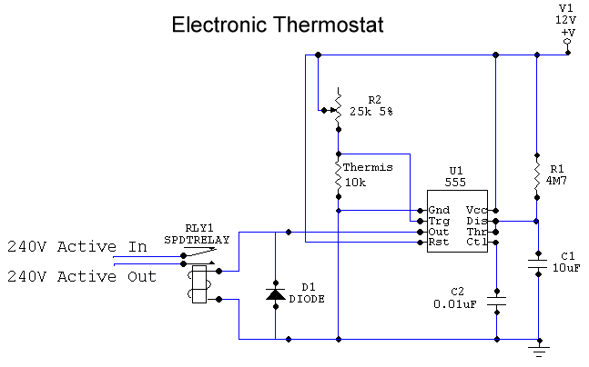
The resistance of the thermistor decreases as it heats up.  The variable resistor R2 is set to a value such that when the the temperature rises above your set value, the voltage across the thermistor falls below 1/3 of the supply voltage.  This turns on the output of the 555 chip, which switches on the relay.  The output will stay on until the temperature drops enough to bring the voltage across the thermistor above 1/3 of the supply voltage, at which point R1 and C1 ensure that it stays on for an extra 50 seconds or so (this is to prevent the compressor being switched on and off too rapidly).


This is how the prototype currently stands.  I was intending to use a low-power CMOS version of the 555 chip to extend battery life, but now that I'm planning to add a rechargeable battery (that charges when the freezer motor is running) I'm not sure that the efficiency improvement is worth chasing.


I'm still trying to improve the efficiency of the old freezer, so I visited the scrap metal guys on the weekend and found a nice bit of extruded aluminium channel (about 140mm wide and 600mm long).  I'm planning to attach it to the hottest part of the freezer body and have a couple of old PC power supply fans blowing on it.  They will be driven via a transistor, which is switched on by the output of the 555 chip (so the fans will be on when the relay is on).


As I said before, it's all good cheap fun. ;-)


BTH

« Last Edit: February 06, 2006, 10:54:54 PM by (unknown) »

BT Humble

  • Sr. Member
  • ****
  • Posts: 475
Re: Electronic Refigerator Thermostat Schematic
« Reply #1 on: February 06, 2006, 04:39:18 PM »
If you can't see that schematic clearly, you can view a full-sized image by clicking here.


And of course I meant to write "Refrigerator" instead of "Refigerator"! :-(


BTH

« Last Edit: February 06, 2006, 04:39:18 PM by BT Humble »

zap

  • Hero Member
  • *****
  • Posts: 1107
  • There's an app for that
Re: Electronic Refigerator Thermostat Schematic
« Reply #2 on: February 06, 2006, 11:44:39 PM »
Very nice BT, looks simple enough even for me. Does any value work for D1?


BTW... Do they grow many figs in Fiji? : ) I guess a biologist might call it a refrogerator?

« Last Edit: February 06, 2006, 11:44:39 PM by zap »

Bruce S

  • Global Moderator
  • Super Hero Member Plus
  • *****
  • Posts: 5422
  • Country: us
  • USA
Re: Electronic Refigerator Thermostat Schematic
« Reply #3 on: February 07, 2006, 07:55:33 AM »
BTH;

 Very nice and simple design. Even easy enough to adapt for 120Vac , by just changing the relay.

How sensitive is the switching? does it depend on the thermistor for exact temperature or do you have a "fudge" factor built in?

Good idea to for the time constant to let it run just a bit longer.

One small idea you might want to try. Since cooler air is always closer to the floor, try turning the fans around so that they are pulling the heat out away from the heat rather than blowing air around them. This should work similar to the way computer fans are pulling heat out of the cases.

My uncle, use to pull the old insulation out and shot the expando foam into where the fiberglass was. He would put banding around the sides of the unit, take the top cover off pull the fiberglass out and shoot the foam in with long straws and just let it fill upwards. had the effect of having a freezer that would keep deer meat cold for a couple days even with the power out, all the newer freezers arounf here are done this way now.


Hope this helps

Bruce S

« Last Edit: February 07, 2006, 07:55:33 AM by Bruce S »
A kind word often goes unsaid BUT never goes unheard

ghurd

  • Super Hero Member Plus
  • *******
  • Posts: 8059
Re: Electronic Refigerator Thermostat Schematic
« Reply #4 on: February 07, 2006, 08:30:39 AM »
Curious about why 50 seconds. The parts were on hand, aimed for 1 minute but 50 seconds is fine, or was 50 seconds determined some how?

G-
« Last Edit: February 07, 2006, 08:30:39 AM by ghurd »
www.ghurd.info<<<-----Information on my Controller

BT Humble

  • Sr. Member
  • ****
  • Posts: 475
Re: Electronic Refigerator Thermostat Schematic
« Reply #5 on: February 07, 2006, 02:58:59 PM »
Very nice BT, looks simple enough even for me. Does any value work for D1?


I used a 1N4004 rectifier diode, but I expect pretty much anything rated at an amp or so should do. It's just to provide a path for the back EMF when the relay coil is switched off.


BTH

« Last Edit: February 07, 2006, 02:58:59 PM by BT Humble »

BT Humble

  • Sr. Member
  • ****
  • Posts: 475
Re: Electronic Refigerator Thermostat Schematic
« Reply #6 on: February 07, 2006, 03:03:46 PM »


Very nice and simple design. Even easy enough to adapt for 120Vac , by just changing the relay.


How sensitive is the switching? does it depend on the thermistor for exact temperature or do you have a "fudge" factor built in?


It's pretty sensitive, and depends solely on the thermistor.  Once you seal your thermistor inside some heatshrink tubing it takes a few seconds for changes in temperature to get through to it though (I did the early testing by swapping the thermistor "probe" between a glass of ice water and another of hot).


Good idea to for the time constant to let it run just a bit longer.


As it turns out, that might not be so necessary (due to the slow-reacting probe, as I mentioned earlier).  It can't hurt though, since you have to have the components there anyway.


BTH

« Last Edit: February 07, 2006, 03:03:46 PM by BT Humble »

BT Humble

  • Sr. Member
  • ****
  • Posts: 475
Re: Electronic Refigerator Thermostat Schematic
« Reply #7 on: February 07, 2006, 03:15:40 PM »


Curious about why 50 seconds. The parts were on hand, aimed for 1 minute but 50 seconds is fine, or was 50 seconds determined some how?


You were right with the first guess.  I reckoned that a minute should do the job, and already had a 10uF capacitor soldered to the board, and had a 4M7 resistor in the box (technically giving 47 seconds, but with a 5% resistor and a 10% capacitor there's a bit of "dunno" in there).


The next size up in the E12 series is a 5M6, which would have given 56 seconds (5,600,000 Ohms * 0.00001 Farads = 56 seconds), but I didn't have one handy at the time.  Alternatively  if you were really determined to get your full 60 seconds you could use a 2M7 and a 3M3 resistor in series to get 6M ohms. ;-)


BTH

« Last Edit: February 07, 2006, 03:15:40 PM by BT Humble »

Bruce S

  • Global Moderator
  • Super Hero Member Plus
  • *****
  • Posts: 5422
  • Country: us
  • USA
Re: Electronic Refigerator Thermostat Schematic
« Reply #8 on: February 08, 2006, 04:53:05 PM »
BTH:

   Thanks for the input. I think as it turns out the slow reacting and time constant would both be a great help to keep the motor runs having quick stop/starts due to quick temp changes.

Hope you don't mind , but I think I'll build one of these little guys and actually try it on an old bar fridge given to me as yet another "project" the timer is shot and keeps freezing stuff, including my beer.-(

Will merely bypass it and put one of these little guys in there.

And as you pointed out, the extra run time will be whatever I have on hand.


Cheers

Bruce S

« Last Edit: February 08, 2006, 04:53:05 PM by Bruce S »
A kind word often goes unsaid BUT never goes unheard

BT Humble

  • Sr. Member
  • ****
  • Posts: 475
Re: Electronic Refigerator Thermostat Schematic
« Reply #9 on: February 08, 2006, 07:19:55 PM »


Hope you don't mind , but I think I'll build one of these little guys and actually try it on an old bar fridge given to me as yet another "project" the timer is shot and keeps freezing stuff, including my beer.-(


Mind?  Of course not!  I mean, if I'd wanted to keep it secret I wouldn't have told you in the first place, now would I? ;-)


The simplest way to power the circuit would be to just use a small 12V plugpack.  It'll use a few watt-hours per day, but if you're going to be running from the mains anyway that shouldn't be a problem.


I picked up a couple of suitable plugpacks (12VDC, 200mA) from the bargain bin at my local Jaycar the other day for $5 each, it might be worth a look of you have one nearby.


BTH

« Last Edit: February 08, 2006, 07:19:55 PM by BT Humble »