This write up is primarily designed to be a tutorial for beginners to small shaded pole motor conversion. The conversions shown in this tutorial are not pretty and polished looking by any means as most of these are pretty much the results of repeated experiments with winding and rewinding, glueing on, removing and reglueing magnets many times to improve cogging or output capabilty. Most of the glue jobs are done with super glue and hot melt for a less than permanant unit in case additional modification is needed. Hopefully a few techniques or bits of insight may provide for the new experimenter to be more sucessfull in their own box fan motor conversions.
Although I had experimented with the conversion of a shaded pole 20 inch box fan motor back a couple of years ago, I became more intrigued when about a year or so ago there were discussions in a post where several folks talked about a possible contest to try to get 10 W at 10 mph for under $10 out of one of these motors. The one I had previously converted was good for around 15 Watts at 1000 RPM using the stock windings and ceramic magnets (Lowes 1-7/8 X 7/8 X 3/8 cut in half); however I presumed that one could do better. So I took the motor out of an old 20 in fan (vintage about 1965) that I had inherited from my parents and started experimenting.
Using the same 1/2 Lowes magnets and stock windings of about 1200 total turns of stock AWG 24 windings, once again I got about 15 W at 1000 RPM. I was able to get about 22 volts AC (31 V DC) out of the conversion at 1000 RPM, which seemed reasonably suited for a 3 ft prop but the most significant shortcoming to use it for 12 V charging was the relatively high DC resistance and high inductance of the windings (13.5 Ohm dc resistance and a total of about 24 Ohms ac impedence @ 1000 RPM) This meant that for every amp of current I tried to draw from it, the voltage drop inside the windings would be about 24 Vac, resulting in nothing on the output. In other words the shorted out current capability was only about 0.9 amps. I experimented with dividing the 1200 turns contained in the 6 poles (200 turns per pole) into two sets of 3 poles in series working in parallel with the other 3 poles. This obviously cut the output voltage in half but resulted in the output impedence being reduced by a factor of 4X. So now I had a unit that at 1000 RPM would put out 11 VAC (15.5 V DC) and had an output impedance of around 6 ohms. Much improved except the output RPM / DC Volt rating was around 64.5 RPM/V and cutin for a 12V battery (13.4V charging) would be almost 865 RPM which is pretty high for 3 ft prop if I wanted the cutin wind speed to be around 6 to 7 mph. A much smaller prop than 3 ft diameter (or high TSR) would have difficulty starting one of these conversions in less than a 8 to 10 mph wind. So I decided to cut out the old windings and rewind it with a larger diameter wire, and also try using some small 1 X 1/2 X 1/8 inch neos I had bought from Windstuff Ed. The following pics and words will help explain how I did that and add insight into some of the above.
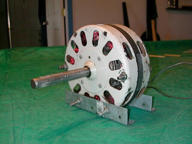
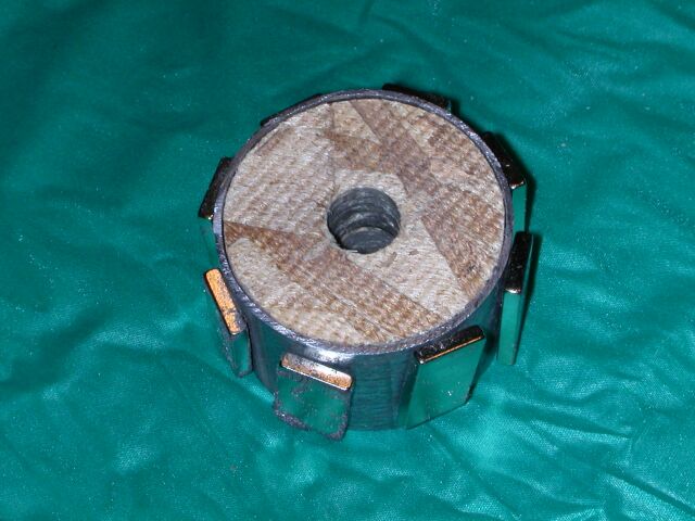
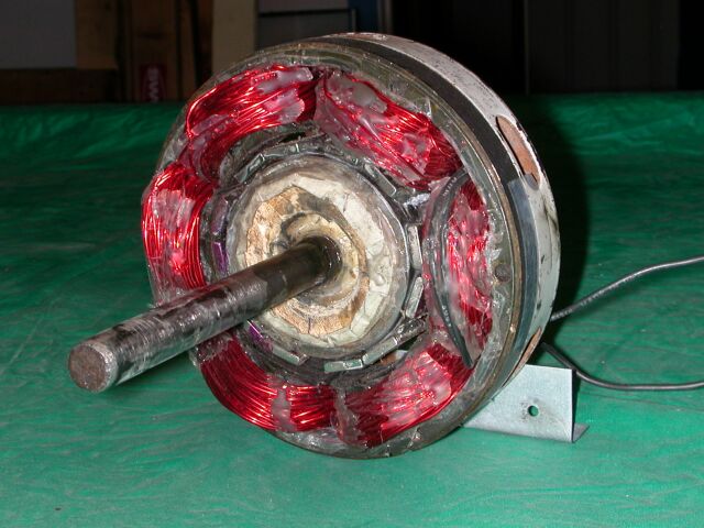
This (above) shows the final product of the box fan motor converted with new stator windings, a new longer shaft, 6 magnet poles using 2 each of the neos per pole (single phase operation).
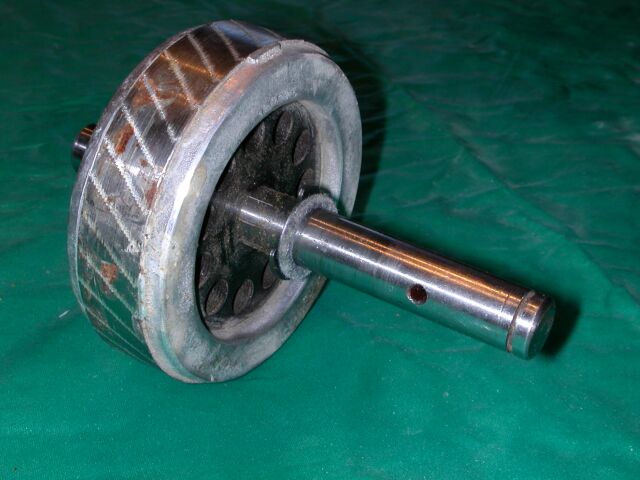
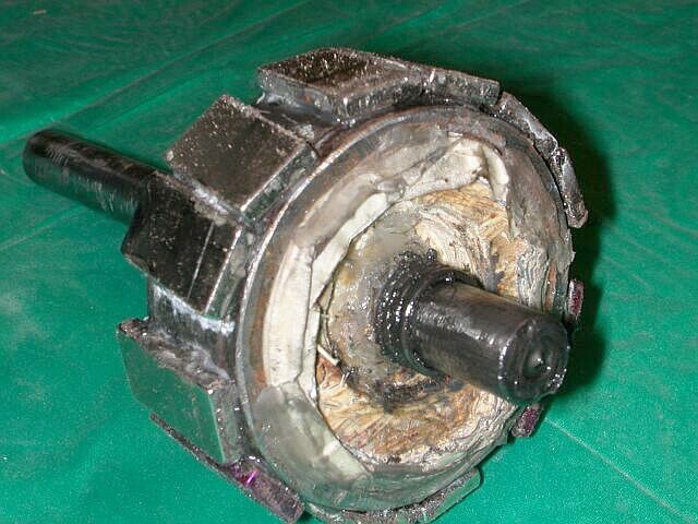
Although this is not the armature in the white fan motor conversion, it is an original armature out of one of these box fan motors. Had I decided to use the thin 1/8 inch thick neos in the white motor to start with, I might have just tried grinding down 6 flat areas, corresponding to the 6 stator poles, on the original rotor to mount the magnets; but since I started out using much thicker 3/8 in thick Lowes ceramics cut in 2 pieces I did not want to do that much grinding, so I came up with the idea to build a new rotor using the original shaft with the rotor pressed off. I looked around and found some pipe that was the correct size such that once the 3/8 thick magnets were mounted to it, they would fit with a small amount of clearance inside the stator. I then cut out disks from OSB board (chip board, although plywood works well also) that would fit inside the pipe, and bore out a 1/2 inch diameter center hole to re-insert and super glue the original shaft. I later built a new rotor from a larger diameter piece of pipe that I used to mount the neos. The following pics show various stages of this new rotor assembly.
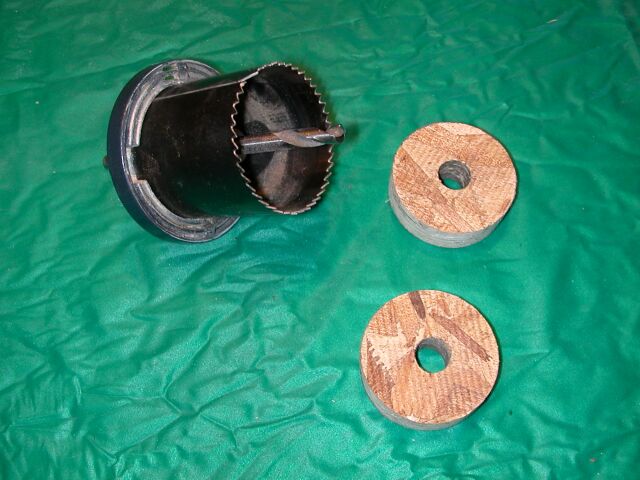
The disks are cut out with a drill type hole saw. If there is a gap between the outside diameter of the disks and the id of the pipe, I usually wrap masking or duct tape around the wooden disks to make for a snug fit, then squirt in some super glue to glue it all together.
Above is an assembly with 8 neos for use in a 3 phase (8 magnet, 6 stator pole) unit.
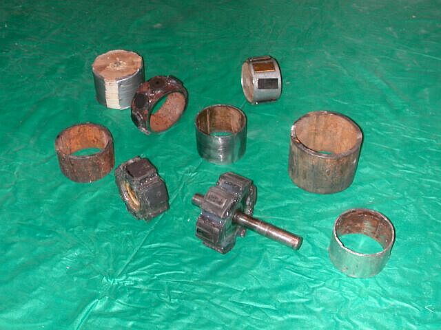
Above shows various pieces of pipe, conduit, etc for use in various assemblies.
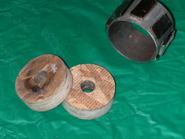
This is a rotor (minus the shaft) using the Lowes 1/2 ceramic magnets that I initially used in the white fan conversion.
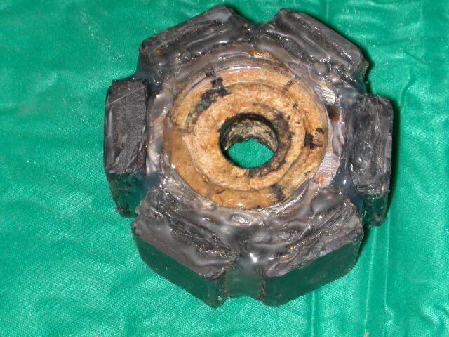
Above is the rotor assembly presently used in the white fan conversion. I initially tried using 6 neos but they were not too much better than the ceramic magnets and because they were so narrow relative to the face of the stator poles the was alot of cogging. So I mounted 2 each side by side X 6 sets to line up with the 6 stator faces. NN - SS - NN - SS - NN - SS The magnets are somewhat skewed to reduce cogging. Surprisingly this rotor only presents about 1.5 ft ounce of cogging torque but the gap between the magnet faces to the stator pole faces is about 3 to 4 millimeters. If the gap were closer I think the cogging might be worse.
Now comes the stator modifications. Most of these small shaded pole motors come with multiple windings using anywhere from AWG 24 to AWG 27 wire. The more speeds the fan has the more complex the wireing arrangement. One can try to determine the number of turns, DC resistance, wire guage etc to try to find a useful combination of parallelling windings, or poles etc to get some useful results, and I have done this on several units, but all in all, if the original windings are not larger diameter than AWG 24 wire, it is easier to just remove the original windings and rewind it with the appropriate number of turns of a wire size that meets your design needs. One way to try to determine the number of original turns if you have already built a rotor assembly to make the original stator at least work as an alternator is to wrap maybe 25 separate new turns of say AWG 24 wire around one of the stator poles and bring those leads out through the case and crank up the alternator with a drill or lathe or whatever at some known RPM and take a reading of the AC voltage to come up with an RPM per Volt number so that you can determine how many turns you might need altogether on a rewound stator. Or compare the output voltage of the newly added windings to the output voltage you get off one of the original windings and find the ratio. For example, if you are getting 2 volts out of the 25 new added turns and you get 30 V out of one of the original windings you know you have an output of 25 turns per 2 volts or 12.5 turns per volt on the new windings X 30 volts on the original winding gives 375 turns on the original winding or 62.5 turns on each of the 6 poles.
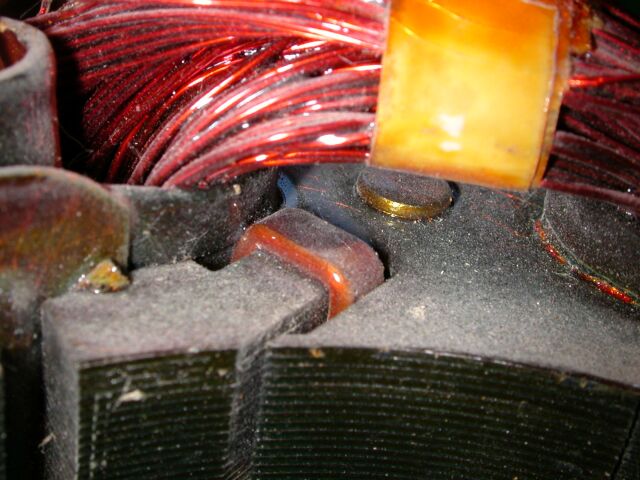
The above pic shows a closeup of the shunt found on each pole in these shaded pole motors. This is what gives these types of AC motors the ability to start since they do not have a separate start winding. This is just a heavy copper band that effectively shorts out part of the pole region. I usually try to remove these shunts especially if I take out the original windings. If you are going to use the original windings you might cause more damage to the windings trying to removethe shunts than what it is worth. Ive measured - although not very precisely - the effects of having them in verses removed and I think the performance is better with them removed; however leaving the shunts in is not a real show stopper.
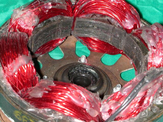
Above is the white fan motor stator rewound with AWG 18 (1 MM diameter) wire. I was able to get 100 turns on each pole, and as you can see its not wound the neatest job in the world. The white gue is hotmelt glue just to keep the winding from shifting around. When I finally get the units done where I care not to do any more modifications I usually coat the stator coils with a couple of heavy coats of spar urathane varnish to set them in place. When rewinding these stators you must be sure that the cardboard / phenolic / painted on insulator material that sits down in the cavity is intact. If not the new windings will get the enamel insulation damaged as it bends around the corners of the laminates, and it will short out the windings to the laminates. There is nothing worse than spending a couple of hours tediously winding several hundred turns of wire on a stator only to find the wire is shorted to the metal laminates. In this particular motor it used a heavy cardboard as the insulators (typical of a 40 year old motor) on the laminates and I damaged them significantly tearing out the original windings (they were a bit brittle from age I think) so I reinsulated the cavitys using several alternating layers of masking and scotch tape. It probably wasn't the best thing to use but as I said in the beginning I was just trying to get something built to experiment with - to see if I could get more power out of one of these units. When rewinding you also have to be careful not to nick the enamel insulation as you pass the wire through the narrow slot between the poles. On one unit the gap was so narrow that I took a file and filed off a millimeter or so on each of the sides of the T tops on the laminates to get more space to easily run the wire through, and then added a layer of scotch tape on the ends of the T s to buffer the wire from being scratch by the raw laminate metal.
Once you determine how many turns of wire you think you need to get the output you want at a give RPM, you can estimate how many feet it will take by estimating the average diameter and calculating the length for each turn. (assume a more or less round winding around the pole stump) Don't just measure around the pole stump and assume that as the final size as the diameter will increase as the turns build up. Then pick a wire size that will enable you to get that many turns on. I really see no need to use larger than AWG 18 wire in these little motors, and probably the best size to use is AWG 20. If you are going to need alot of turns because you want to generate fairly high voltages for say 24 or 48 V use you may want to use no larger than AWG 22 or 24. And if your wanting higher voltages than that you may as well keep the original windings and add more turns on top of them and connect the end of the original winding to the start of the added windings to put them in series to get the higher voltage. I have found that I can get in the neighborhood of 0.005 Volts AC per turn per 100 rpm with the 1/2 Lowes ceramic magnets (single phase) and about 0.0083 Volts AC per turn per 100 RPM with the two neos on each of the 6 poles (single phase). These numbers vary somewhat (+/- 30 %) depending on the spacing of the magnets from the stator pole faces and what size the stator is and several other variables but it gives you an idea of what to expect.
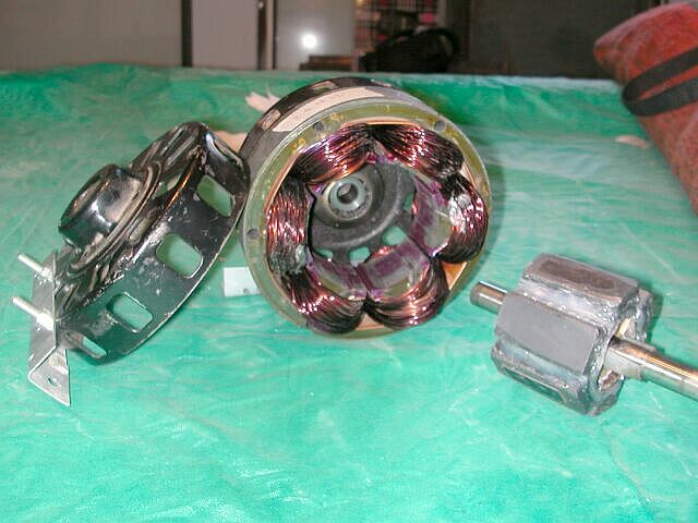
The white fan alternator ready for the front cover to be put on.
This is a pic of a slightly larger (1/12 horsepower) shaded pole motor that I converted using the full size of the Lowes magnets, since the stator thickness was about 1.25 inches thick, I use the full magnets to get coverage over the entire thickness. On this unit it was already wound with 60 turns of awg 20 on each of the 6 poles, so I added 30 additional turns per pole of AWG 20 for a total of 540 turns to get the output to what I wanted. I kept the tap where I joined the new windings to the original and brought it out so I have a unit that will put out at around 30 RPM/V dc (original winding) or 20 RPM/V dc both winding in series, or 60 RPM/V dc new winding only.
The white fan alternator with the 12 neos has the following specs:
- neos 2 each on 6 poles
- turns total (100/stator pole) AWG 18 wire.
- V DC output at 310 RPM
DC resistance of windings: 1.4 Ohms
Ac output impedance at 60 Hz (1200 RPM): 5 Ohms
Power capability into a 13.3 V Battery at 1000 RPM 5.1 Amps (68 Watts)
When driven by a 4.15 ft diameter 3 blade prop, (TSR=4.4 approx)
Cutin slightly over 6 mph
@ 10 MPH windspeed 1.6 Amp into the Battery
@ 15 MPH 4.2 Amps into the battery.
Johnlm
