Thought it was about time I got back to some of this, and bring you all up to date with what I'm doing.
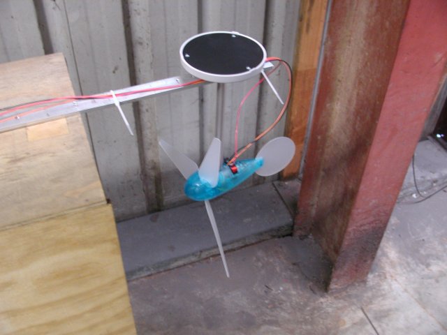
I mentioned a long time ago I had a wind tunnel at work, but it was really too small for much practical application. I've also been working on an mppt system. I really need a working wind generator to progress the mppt. And Jaycar now sell a toy wind generator kit, which makes a whole 10 volts at 100mA. So I put all these things together, and this is where I'm at.
Here's a few photo's.
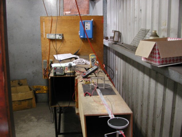
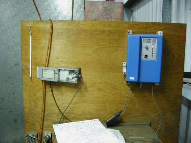
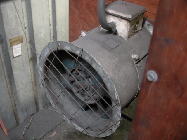
We use the wind tunnel to calibrate air velocity sensors for ventilation systems in coal mines. It's about 12 inches square. The big blue box is the motor speed controller.
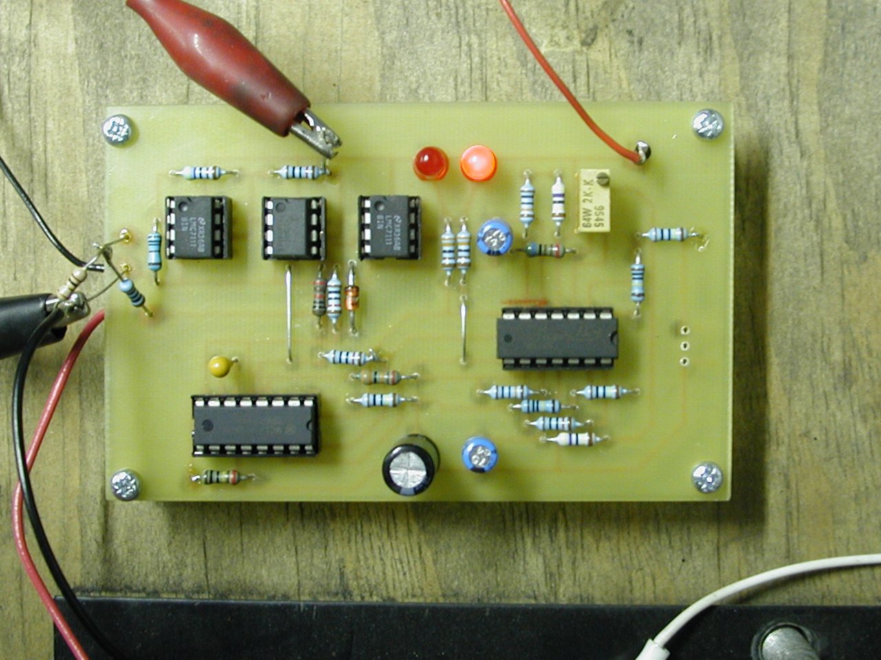
The pcb is the prototype mppt controller. For those that can follow this, here's a brief explanation. A 4046 PLL is used as an oscillator to modulate the control voltage for the pwm. The 3 small op-amps give a signal derived from the generators output power. The first is a current amplifier, the second is an OTA analog multiplier (current times voltage = power), and the third is a differentiator. The 4046 includes a phase comparator. The 2 inputs to the phase comparator are the modulation signal and the power signal. The output of the phase comparator is integrated & becomes the dc control voltage for the pwm. There's also an input from the tacho, to quickly push the control voltage in the right direction as the wind changes.
So, if the pwm modulation and the power feedback signal are in phase, we keep increasing the pwm control voltage. If they're out of phase, we decrease the pwm control voltage.
Apart from some basic functional testing, to verify parts of the circuit behave as expected, I've yet to do any full-blown testing. Anyway, I've yet to actually build the pwm circuit, and a fet. I'll probably just run the wind generator up by itself, and plot some figures. Then use the fet as a load, and verify that it gets to the mppt point for each applied windspeed.
Amanda
