If it's a choice between two rules of thumb:
"first and last magnets aligned over adjacent slots",
and
"skew the rotor by 10 degrees to de-cog",
I'd go with A)
Comparing the rotor of your motor to mine, yours has a smaller diameter, but is 2x
as long. The rotor I will convert is 5.5" in diameter and 2" long. The same skew
angle should be used on your rotor and mine. The resulting helix angle would make
yours look very different than mine, but that's not what we're after.
Permit me, then to refer to first principles (A collective sigh from the non-geeks
out there; I can hear you). But I know you're a mechanical engineer, so I'm sure
you will relish this. :^)
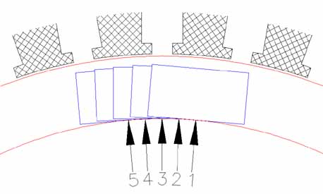
In the first view, five (5) magnets are arranged on the rotor in a skewed fashion.
The stator teeth are visible above. I assumed that there are 36 teeth in the stator.
The rotation between #1 and #5 is 10 degrees. Mag #1 is currently aligned with
the top stator tooth, Mag #5 with the tooth to the left. Both are as close to
the stator tooth as they're going to get, and their magnetism would keep them
there, because the are attracted to the iron teeth. Mag #3 is in between teeth,
so it could go either way. Mag's #2 & #4 are attracted to opposite teeth;
their pulls cancel each other out.
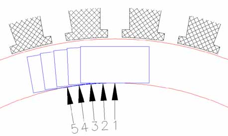
In the next drawing, the rotor has rotated by 5 degrees. The magnet closest to
a stator tooth is #3. Mags #1 and #5 are between stator teeth. Mags #2 and #4
are attracted to the same tooth as #3, but on opposite sides, so their pulls
cancel out again.
I haven't shown intermediate positions, but when I tried them in CAD, and measured,
I found that magnets tended to pull to one tooth more than another.
When you look at it from a "Potential energy" point of view, then the first
position has the lowest PE, this is where the motor will prefer to cog to.
The second position also is a low point of PE, but not as low as the first.
Intermediate positions had a preference for one tooth or another, but two
magnets are still cancelling each other's cog, like in the other two points.
Picture a sine wave with a harmonic in it that makes one valley lower than the
next valley. Compared to the original sine wave, with higher peaks, less
energy is required to get over each peak. It takes now less torque to start the rotor.
Therefore, this skewing is not so much "DE-cogging", but "LESS-cogging".
I hope this helped.
If there is any arrangement of magnets that further improves on this geometry,
then it would be of benefit to investigate.
