Author Topic: ECM in Arkansas  (Read 972 times)

0 Members and 1 Guest are viewing this topic.

RogerAS

  • Sr. Member
  • ****
  • Posts: 329
ECM in Arkansas
« on: June 20, 2006, 01:26:49 PM »
Hi All,


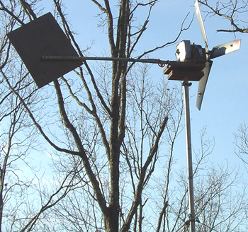
Here's one of my 2 GE ECM turbines. Yeah, it's on a short pole-tower, but it's what I got. I wish I could retro fit one with arc segment neos on the rotor. I'm sure it could get past the pitiful 5 amp limit then. I've tried Jerrys seperation of the fields and individual rectification, but I saw little or no improvement. These have a nice electronics package hung on the back, and both of mine had a single blown capacitor. I've used the mosFETs and other parts in little projects, including my Ku band sattelite reciever based solar panel tracker. I'll post my very own design for the drive schematic soon. That circuit uses the fact that the sun only travels in one direction with 2 NE555's to time control movement, (hint). I have a set of Jerrys blades on both, with my own mods. I thinned the trailing edge, rounded the tips a little, and cut off the root tab, moving the mounting bolts into the body where it's stronger, and they work sweet. I don't sandwich them, just used some good sized washers between the bolt head and blade. The hub is from a big central air conditioning fan, and fit the 1/2" motor shaft perfectly. I barely had to tweak the attack angle. You'll notice the bumps out from the root. These were balancing weights, and have been moved back in to the root since this photo. Also you'll see that one blades has a bit of red paint out towards the tip. This was a balancing aid. I could tell if the blade in front or behind the red balde was out, or the red one. I helps a lot on these blades, as the uniform blackness can make it confusing.


The pivot point is a Ford rear axle bearing sandwiched between 2 plywood plates. The lower plate has a oversized hole that doesn't touch the pole. The box on the back is a nice thick aluminum housing that hides the bridges and BIG capacitors. It also has heatsink fins in the top. That's where the origional electronics were housed. No, it does't have furling. I'm not sure I'm smart enough to build that. The tail boom is a scrap of C PVC (1") Schedule 40 with a hunk of 1/4" plywood as the tail. So far they've survived well over 80mph winds, as we had a close call with an F1 last November.


I cut 4 chunks of 3/4" plywood to match the radius of the motor and a bolt pinch strap to lock that to the motor to a doubled 3/4" plywood base where the radius parts mate to the base. All Scrap.  The harware, wood, blades and everything else cost me around $45 total. So for my 12V ECM turbine I'm spending $.75 per watt, aprox.


I'm still looking for the 1 HP version of this motor, and more of this kind. But they're getting hard to find.


I'll post some more later. Thanks for the bandwidth Otherpower!


RogerAS


PS see postings:


http://www.fieldlines.com/story/2004/3/22/9835/59954


and


http://www.fieldlines.com/story/2004/3/18/113923/780

« Last Edit: June 20, 2006, 01:26:49 PM by (unknown) »

RogerAS

  • Sr. Member
  • ****
  • Posts: 329
Solar Panel Tracker Schematic
« Reply #1 on: June 21, 2006, 06:32:13 PM »
Hi All,


Well, as promised here is the schematic, link below, for a solar panel tracker. It uses 1 LM324 quad opamp, 3 n-channel mosfets, 2 NE 555's or 1 NE556. 2 double pole double throw 12V relays and a handful of other parts. 99% of my parts were salvaged from mircowaves, TV's, and other junk electronics. I enclosed mine in a weatherproof plastic box and hang it on the Ku band sattelite dish pole. The CDS cell #3 tells the circuit that the sun is shining bright enough to bother, and #2 is a semi shaded opaque blocker facing east. CDS #1 is set to reverse the tracker when it gets really dark in the evening. I used the relays cause I couldn't find any p-channel fets or H bridge transistors. Maybe I just ain't smart enough to figure out another way to do it. These realys are still working about a little over year after building this so why bother? Here's the deal. Aside from Biblical references of the sun reversing its path the old star tracks east to west every day. CDS#3 will turn on the signal to allow CDS#2 to start timing cycles as the sun tracks. If the tracker tries to go too far CDS#2 is put in the shade and the pulses stop until the sun catches up. It never reverses looking for the sun and wastes power hunting. The First 555 (mutivibrator) can be set to keep up with the sun in lillte bity or long cycles and the second 555 (one shot) determines how long those pulses are sent to the drive motor. Different motors will require different settings. Pay real close attention to the bigger timing caps. You might have to alter their values. It took me about 2 days to get things set, but it tracks real good now. I put a little buzzer from a burned out UPS on there to help know when it was being pulsed. Since then I have unhooked it. I removed the switches from the actuator and made some stops out of wood and used wetherproof low resistance switches as movement limiters. The actuator switches had big diodes I felt robbed power.


The CDS cells are in individual Tostitos dip jars, packed with wadded up walmart sacks, the metal lids screwed to wood blocks, and the jars screwed into the lids with a dab of silicone sealer around the threaded lip. I ran the output of these to my control box inside vacuum tubing with more silicone at the ends. CDS #2 has a hunk of innertube across the north-south axis about 1/2 across the jar bottom way put CDS#2 into the shade if the tracker gets ahead of the sun. This is also glued down with silicone. Heck, black silicone itself would work.


I noticed a marked increase in the day to day output of my panels after activating the tracking. Now If I can get a good MPPT in the 60 amp range I'll be set. Right now I have 2-BP75's, 2-Sharp123's, 2-Kyocera125's with 1-25W oddball babysize they sell to maintain car batteries. Currently I use a Trace C40 that replaced a Morningstar 20. My panels output are individually run to a fuse panel from a Ranger pickup truck, and then combined into a 4 GA wire set run to the battery box, about 20 feet away. I love being able to clean my panels from terrafirma! Untimately we hope to have about 1.5K of solar and a matching 1.5K of wind. When our ship runs aground:-)


Comments and suggestions welcome. Please don't commercialize my little schematic, I'm offering it free.


RogerAS


http://www.gobblerguns.com/roger/images/rogertrackerschematic.pdf

« Last Edit: June 21, 2006, 06:32:13 PM by RogerAS »

elvin1949

  • Hero Member
  • *****
  • Posts: 645
Re: ECM in Arkansas
« Reply #2 on: June 22, 2006, 12:43:50 AM »
Morning Roger

 Wish i could find one of those ecm'S.

Oh-well sooner or later one will turn up.

 Nice gennie  THANK'S for the schematic

Added it to my usefull thing's folder.

[hate haveing to hunt for a long time SO.]

thank's

later

elvin
« Last Edit: June 22, 2006, 12:43:50 AM by elvin1949 »