This is the first completed stage 1 of my RE projects list, and only
occurred as a result of finding the Otherpower.com site and others like
Hugh Piggott's. Recently I spat the dummy and quit working for the
multination corporation that had me harnessed for several years.
This has given me the opportunity to finish this project step and start
on many others.
I'd just like to say "Screw corporations! You blokes ROCK  !"
!"
Now for the RE images I promised.
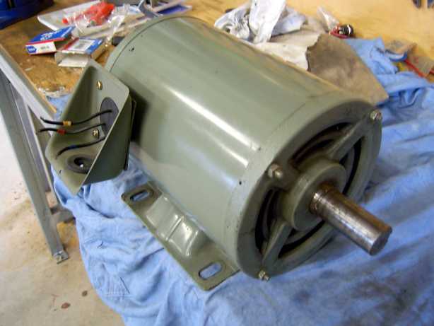
The unit is a Japanese made Fuji Electric 3hp (2.2kW) used 3phase
Induction motor. Looks like a nicely built unit. Spins freely and is a
breeze to dismantle.
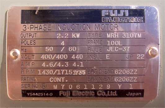
The plate shows it is a 4 pole 415V unit. It's a 36 slot, and I will be
using the existing windings after bringing out three more wires for
Star-Delta selection.
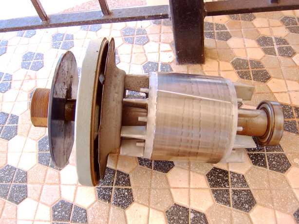
The rotor pulled out. It came with about a 125mm (5 inch) pulley
attached, and I think I might use that for the final installation.
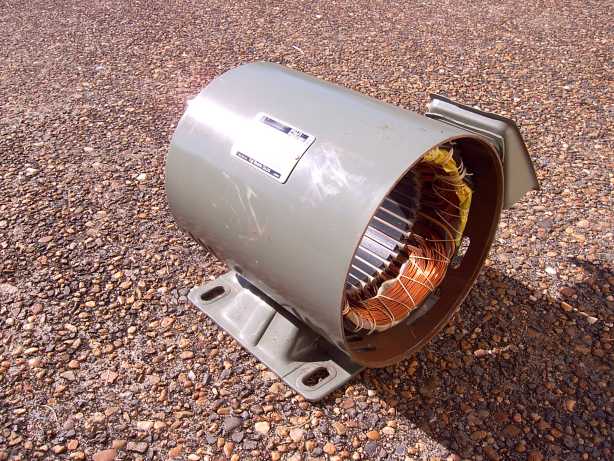
Stator with rotor removed drying in the tropical summer sun. I gave
it a good hose out, and scrub with a tooth brush as there was some
muck in it.
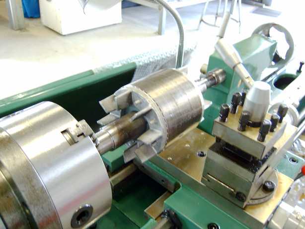
I bought a 2hp metal lathe, and had to test the rotor in it. Even before
I had unpacked it properly and put it up on its stand. 
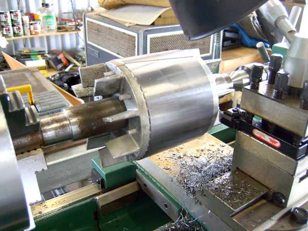
The first pass revealed a nice shiny rotor. I'll be using the 48 of the #18
19mm x 12.7mm (3/4 x ½ inch) Neo's from www.forcefieldmagnets.com.
So I have to machine a good deal of material off the stator to make it all fit
back together.
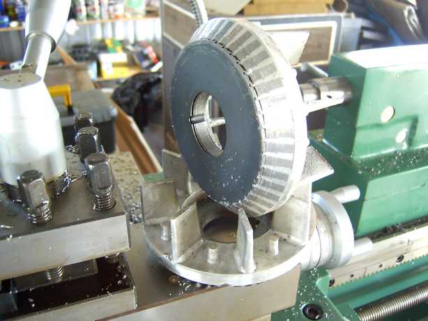
But I hit a little snag. I had to take off so much material, that the alloy fan
ends came off, taking about a dozen laminations with them. I thought that
was curtains for the rotor, but I had a think about it over lunch.
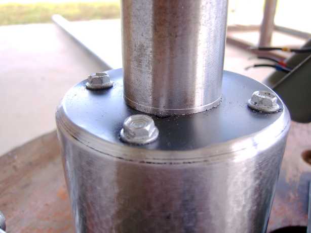
I dug up some 50mm (2 inch) fine thread metal screws, the kind used to
attach a steel roof to steel battens. I found a 3.97mm (no idea in inches)
drill bit and put pilot holes into the laminations. I then oiled the screws
and put them in with a decent electric drill. Four screws into each end, a
quick spin in the lathe and I was back in business 
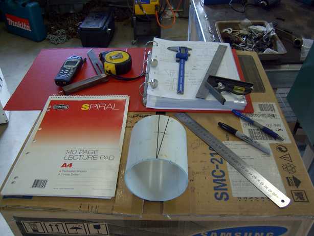
Next step was to start making a rotor cage for the magnets. As this is a
36 slot motor, it requires a 10 degree skew on the magnets. I studied the
diary postings by Zubbly in order to figure all of this out. I am but a hack
compared to the likes of Zubbly 
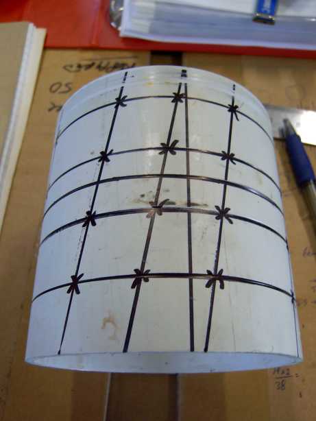
The cage is a piece of 100mm (4 inch) domestic water supply pipe.
Although not as high tech as an aluminium or fiberglass cage, it worked
well and cost nothing.
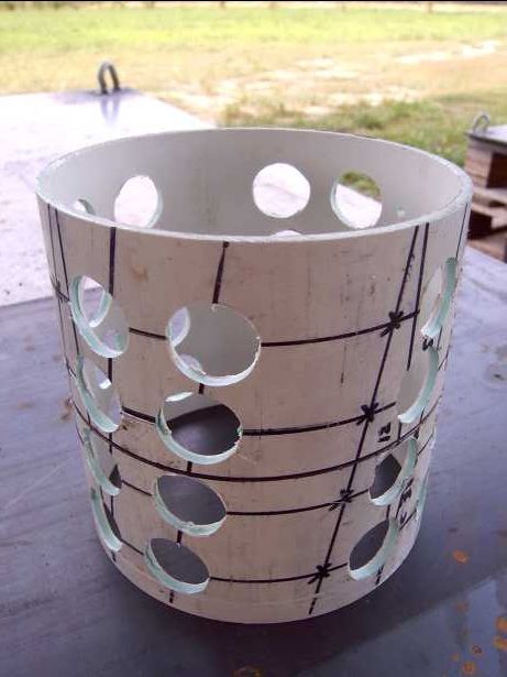
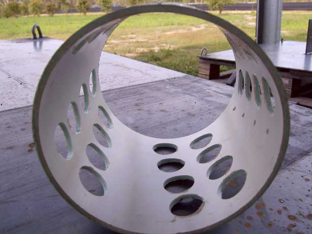
Initially, I had intended to use 3 x 4 groups of magnets for each pole.
But checks showed it would have been too much of a squeeze, and not
enough distance between opposite poles causing possible cancellations.
So its now 2 x 4 groups of magnets for each pole (32 magnets total).
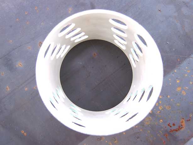
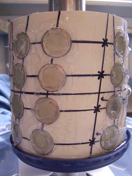
This is the part that worried me the most. Epoxy day. An old food
container lid was a nice fit for the bottom of the cage. And silicone
was used to plug and seal everything. You can see a little bit of leaking
epoxy that the lid caught. I put the rotor back into the lathe once it cured
and machined off any bits that were sticking out.
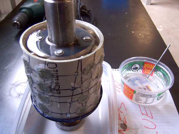
When I first added the Part A and B epoxy together, it was like trying
to mix oil and water. So I quickly cut a piece of arc mesh down to form
a stirrer and put it in the electric drill. By keeping the "stirrer" deep
inside the epoxy, I was able mix it together in less than 30 seconds and
stop bubbles from forming. The rotor was stood up using one of its
bearings pushed part way onto one end. An ice-cream container formed
an emergency spill container. ( I keep all my food containers these days).
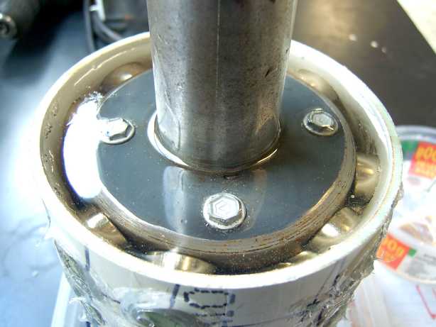
The round magnets allowed all the air bubbles to escape very nicely.
The epoxy completely covers the heads of the screws I had to put in too.
Just to be sure, I ran an orbital sander on top of the shaft for a few
minutes to bring out any last bubbles. It took about 1 hour to show any
sign of curing, and it felt very slightly warm to the touch. I hope this
slow cure will make for a very strong bond.
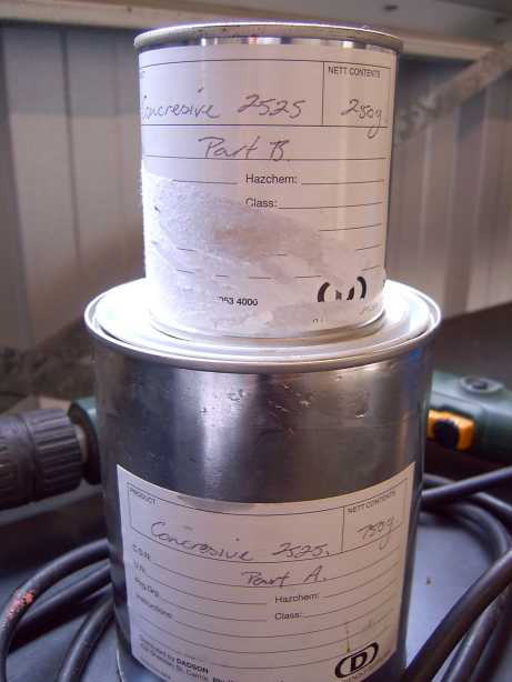
The epoxy I bought was Concresive 2525. Which according to the
confused sales guy, was probably best for metal bonding compared to
the other stuff they had. http://www.degussa-cc.com.au/resrep/resrep9.htm
I would like to try some West System epoxy on the next project. It seems
to be a favorite among the forum users here.
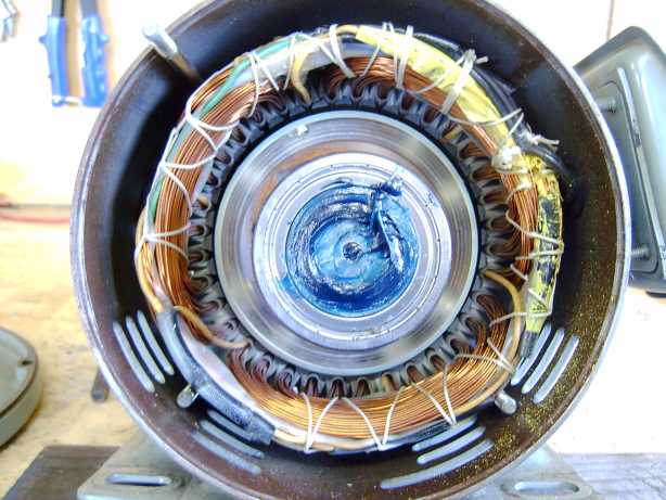
And after a week of curing in the tropical sun, I put the rotor back into
the stator with new bearings. At the bottom left corner of the stator you
can see the internal connection point for the star wiring. You can see
the three yellow wires going into it.
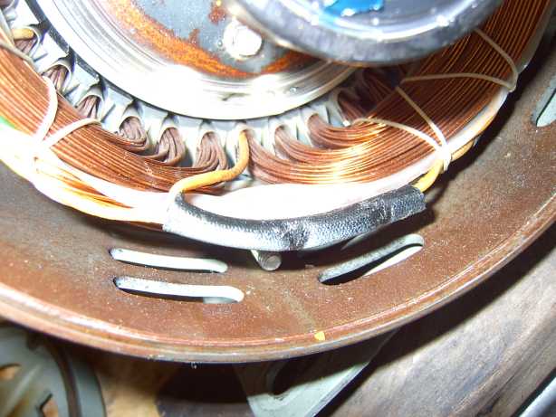
A close up of the star point connection in its black insulation.
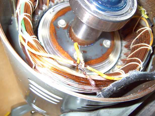
A few snips and it was open and ready for new wires.
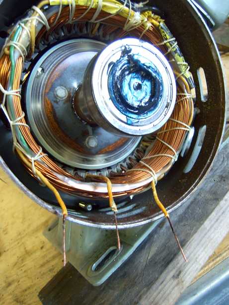
Each wire was cleaned back with fine wet-and-dry sand paper
and then with alcohol.
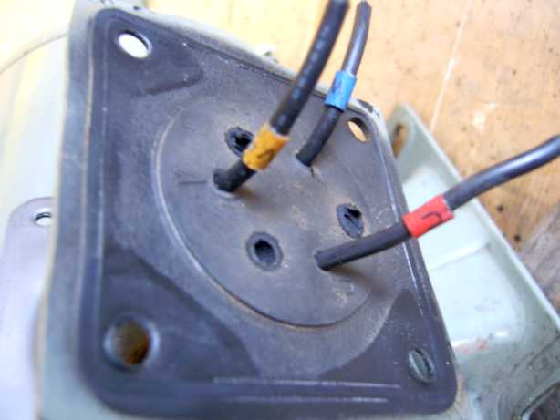
Three new holes were drilled into the rubber cable grommet,
and the wires fit tight.
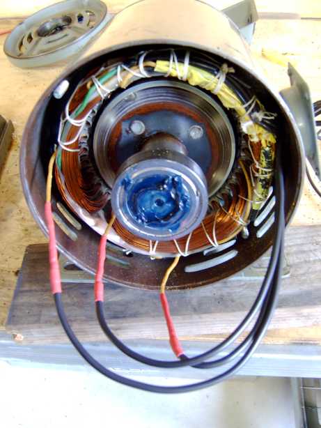
Three new 4mm square double insulated wires, and double
heat shrink connections.
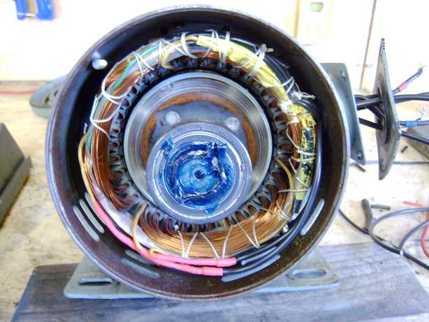
And neatly tucked in, ready for securing into place.
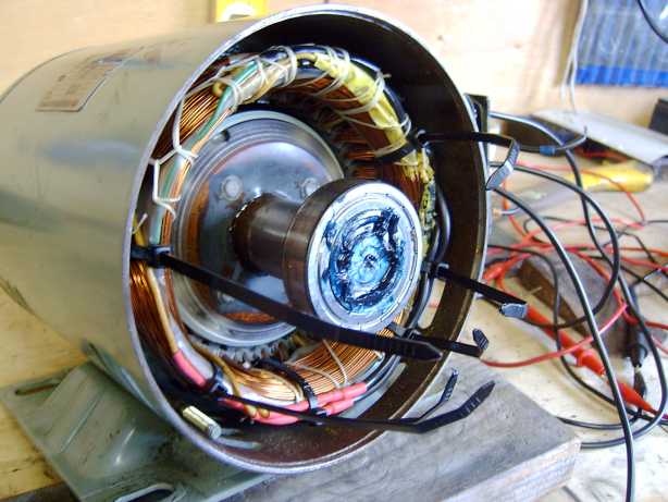
As any Electrician will tell you, cable ties can fix anything.
Hell I know multistory buildings that are held together by the
humble cable tie 
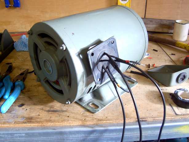
And the termination box with six wires now coming out. I also later
extended the existing three short wires to make termination easier.
Before any other tests I gave the shaft a spin by hand - very nice.
Smooth and can be spun with two fingers.
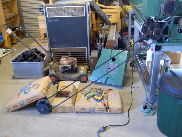
Putting the motor into the lathe chuck was more dangerous than the
setup in the picture. Trust me. And this way if all went pear shaped,
the belt would just fall off the pulley. I'm thinking about an old car
engine from a wreckers for doing this type of thing, with the whole
thing on a steel base frame so I can make infinite readings over the
RPM range.
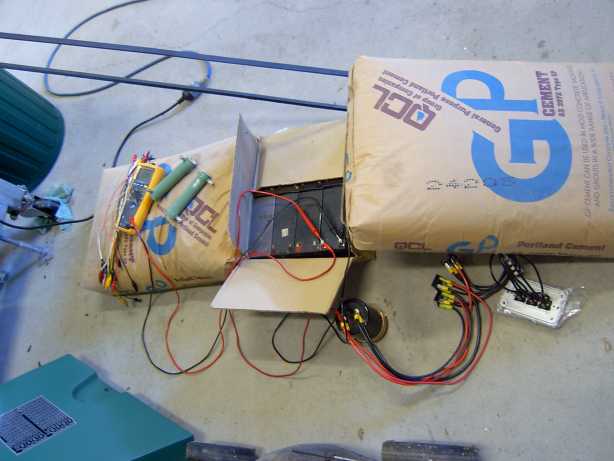
I setup three single pole switches to change between Star and Delta
while testing. The three bridge rectifiers are 1200V 35amp International
Rectifier GBPC2512A. I chose the high voltage units in the hope they
will survive an open circuit voltage condition a little better than the
usual 400V types. The big capacitor is a 400VDC 4,700uF beast from an old
heavy duty 1500VA UPS. Did I mention cement bags are a multi purpose
tool ?
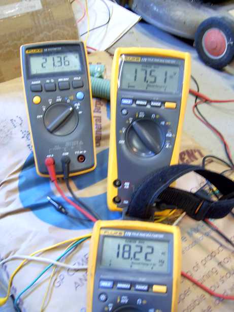
At about 540 RPM in Star into 8x 12V 7Ahr gel cells, all about half flat.
The lathe motor strained under the load, so I only ran each test for about
5 seconds and then let the motor cool off for 5 minutes.
Left meter is showing about 21 amps DC.
Right meter is showing about 17 volts DC.
Bottom meter is showing about 18Hz, which translates to about 540 RPM.
Which all up is about 350watts.
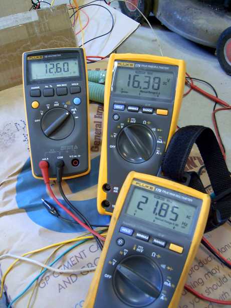
At about 650 RPM in Delta, we see about 190watts.
Left meter is showing about 12 amps DC.
Right meter is showing about 16 volts DC.
Bottom meter is showing about 21Hz, which translates to about 650 RPM.
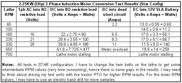
I did some tests in Star mode with the motor shaft in the lathe chuck.
It was dangerous as there was no real way to secure the motor from
the start jolt. For your info, each stator coil is about 6ohms.
In conclusion, I'm chuffed about the whole exercise going so well.
I would call this a 500watt generator to be conservative. I think the
poles are saturated well. A large screw driver will stick to the rotor
shaft. I have 18 x magnets left over and I will use 16 of them to
make a small standard dual rotor design from scratch, with two left
for spares.
An engine/gearbox driven test bed for this and future generators is
on my project to do list.
I'm going to do a set of wood blades from the Warlock calculator a set
them for high torque but low RPM. We have about 15-20km/h
(about 5m/s) constant wind here most days, with gusts to double that.
Oh, and the occasional 300km/h Cat-5 cyclone..... 
I have already modified an old car hub to be the blade hub. Have
bought a 63.5mm (2.5 inch) and a 250mm (10 inch) belt pulley and
will use them in a "speed up" configuration with an MPPT controller
of my design. This should give a 1:4 up ratio and I hope to see an
average of 400-500 RPM on the generator.
Recently we took down a 16m (48 foot) fold over lattice radio tower,
and that will be the new home for the generator with a 6m (18 foot)
pole extension at the top. A total of about 22m (66 feet).
Costs:
Magnets ~AU$300 delivered.
Motor - free
Epoxy ~ AU$20
New Bearings ~ AU$40
Rectifiers ~ AU$18