Author Topic: Building an MPPT booster circuit  (Read 21895 times)

0 Members and 1 Guest are viewing this topic.

elt

  • Sr. Member
  • ****
  • Posts: 328
Re: Picture of MPPT booster circuit
« Reply #33 on: November 10, 2006, 10:37:22 AM »
Reprogramming the Linksys sounds like a cool project. I went and looked to see if any of my wireless stuff was supported but, no... I've used embedded Linux for machine control before; for this part of the system, though, I think that the little $2 chip is adequate to the task. Your post did give me the idea to use the extra pin on the Tiny45 as a 1-wire port for status reporting. Thank you!


... I've been programming computers since dirt was new but I've relied and benefited from the expertise of the folks on this board for just about all of the analog stuff. (Thanks again!) The booster is attributed to Flux's "matching the load" thread (q.v.) He has also posted a thread on a higher current application. If you haven't seen those threads, it's definitely worth searching and reading them. Also, IIRC, Samoapower as posted some info on a high current project that he's starting too.


My mill should put out a kilowatt too. The booster circuit will disconnect to protect itself before then. The main rectifier is external to this circuit and is rated at 800v and 150 amp so it should hold up long after the stator melts! I won't have MPPT at higher powers but the stator is wound to be more efficient at higher powers (rather than in low wind) so I should get more power with lest heat (and therefor less of a tendency to melt) than an no-controller-at-all design. That's the "theory of operations" anyway...


- Ed.

« Last Edit: November 10, 2006, 10:37:22 AM by elt »

mrpackethead

  • Newbie
  • *
  • Posts: 10
Re: Picture of MPPT booster circuit
« Reply #34 on: November 12, 2006, 01:31:34 AM »
The openwrt platform is pretty useful. My first project was to monitor our water storage. ( http://www.frazer.net.nz/wrting/wrtprojects.htm ). A nice easy project. For me the wrt means that things like having an IP stack are available. ITs easy to log etc etc. and its easy to reprogram ( on the fly )..    


I've figured out the major parts of the system to make this work on paper, for a battery based system  In theory at least it shoudl work..   However over the last couple of days i've had a change of mind and think that i wnat to grid-tie and get rid of batterys all together.  


Every time you do anythign with any source of energy, and manilipulate it aroudn theres loss'es, and batterys definitly are in that camp.. from what i can tell, theres at least a 20% loss, once you put the energy in and then take it out again..

« Last Edit: November 12, 2006, 01:31:34 AM by mrpackethead »

elt

  • Sr. Member
  • ****
  • Posts: 328
Testing MPPT booster circuit
« Reply #35 on: January 02, 2007, 06:48:22 PM »
My boost converter has been on the back burner for a while while I worked on the alternator and blades... recent posts got me concerned about efficiency so I thought I should put some current through it and see what I got.


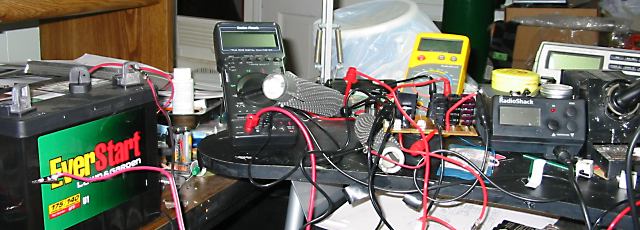
Well, it's kind of hard to see the circuit board in the pic, it's right in front of the yellow DVM. (There's a closeup in the parent of this post.) I changed-out the inductor from my home wound 120uH coil to a 960uH coil I found surplus; I wanted a higher value because I'll be testing the MPPT code by using my 12v solar cells to charge a 24 volt battery and the higher inductor value is a better match to the lower power produced by the solar cells. That said, the 960uH coil is rated for 7 amps so I figured it could stand up to some power too...


I used a 50% duty cycle with no feedback so the output was unregulated; the boost was still 2x but the input voltage on my little batteries sagged with load.


The first three tests were with a 9.6 volt nicad battery pack, the last two with with a 12v lawnmower battery. Various power resistors were used for the load.


  1. ohms, 3.75 watts in, 3.53 watts out, 94%
  2. ohms, 7.05 watts in, 6.62 watts out, 94%
  3. ohms, 15.4 watts in, 13.94 watts out, 91%
  4. 9 ohms, 35.5 watts in, 31.4 watts out, 88.4%
  5. 2 ohms, 63.3 watts in, 54.2 watts out, 85.6 %


Well, it does seem that efficiency is going down as power goes up. One thing I noticed is that output volts were about 2x input volts at lower power, that ratio dropped to about 1.73x at 55 watts. I'm not sure whether I'm not getting the 2x boost because of the circuit itself or whether some unwanted resistance or voltage drops in the wiring... I'll look into that.


- Ed.

« Last Edit: January 02, 2007, 06:48:22 PM by elt »