Author Topic: A Different Alternator - Part 2  (Read 8429 times)

0 Members and 2 Guests are viewing this topic.

SamoaPower

  • Sr. Member
  • ****
  • Posts: 417
A Different Alternator - Part 2
« on: October 21, 2006, 06:11:10 AM »
Part 1 of this diary gave the overview and design objectives of this project. It may be seen here:


http://www.fieldlines.com/story/2006/8/13/7541/74242


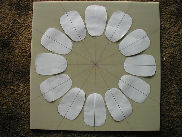
I felt that the construction should begin with the coils since it was anticipated that the actual finished size of them would deviate a bit from the drawings because of winding issues. Sure enough, they came out a little different and since they impact placement on the stator and that, in turn, impacts magnet placement and magnet rotor size, it seemed logical to proceed this way. I notice that many begin with the magnet rotor and I wonder how they handle these issues.


Coil Design

A major factor in determining alternator performance and matching to the rest of the system is alternator efficiency. In turn, coil design has a major impact on efficiency and lack of proper design is probably responsible for many of the numerous failures we see reported on this board.


Low efficiency shows up as excessive heating of the coils and eventual failure at high output levels. Coil heating issues are two-fold. First, is the amount of heat (and attendant temperature rise) generated in the first place and the other is getting rid of that heat to keep the temperature rise below the wire insulation breakdown point.


I like Flux's approach to improved alternator efficiency and matching by increasing the cut-in speed and employing a boost converter to recover low-wind energy. Increasing the cut-in speed (which isn't critical) allows us to decrease the number of coil turns, which allows a larger wire size to be used to decrease coil resistance and losses.


The coils for this 12 volt system have only 13 turns. This was calculated to give a cut-in  speed of 100 rpm which is a 12 mph wind speed for my 16' air rotor. Anything between 10-14 mph should be fine since the energy peak for this site is 16 mph.


I decided to use the commonly available 2x1x.5" N42 magnets to keep costs down. Each of the 16 magnet poles on each rotor consists of three of these arranged in a `T' formation, which approximates a wedge shape. A total of 96 magnets and 96 in^3 are used. The magnet surface area for each pole is 6 in^2. The magnet 0.5" thickness dictates a coil thickness of the same amount to allow a reasonable air gap of 0.75". Nothing need be added for casting. The size of the composite magnet `T' dictates the hole size of the coil.


Given the rough dimensions of the coil, it now remains to select the wire size and winding format. Since transfer of heat from the interior of the coil to the outside surface is by conduction, it is obvious that a very high copper density is desirable, with minimal dead air space between adjacent wires and layers. Dead air is a very poor thermal conductor. To this end, square wire is indicated and is used here and since it has about 20% more copper for a given size, it also has 20% lower resistance. Square wire isn't perfect however, having radii on the corners. It's also a bit expensive.


Crossover of wire in the winding process also introduces an air space, so it was decided to use only one turn per layer since few turns are needed. This produces a spiral coil with no helical component, so no crossovers. To reduce eddy current potential, multiple parallel wires are indicated - the in-hand (so called ) winding. Seven strands of #14 square wire results in a coil thickness of 0.48" satisfying that requirement.


Allowing for insulation thickness, corner radius and a bonding agent results in a copper density of 92%. Compare this to the 60-70% obtained by many. Heat transfer should be significantly improved.


The stator design calls for the coils to also serve as structural elements. This calls for not only high density, but that the coils are well bonded together to approximate a solid block of copper. A few epoxy types were tested and JB Weld provided the best bond to the wire insulation. It also has iron powder filler that should improve its thermal conductance. So, not only does it bond the coil, it also fills in the dead air spaces to improve heat transfer.


I was advised that JB Weld is somewhat magnetic because of the filler. I didn't think the thin layer used would be an issue and indeed, a completed coil exhibits no detectable attraction to a neo.
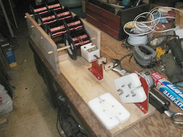

The Winding Jig

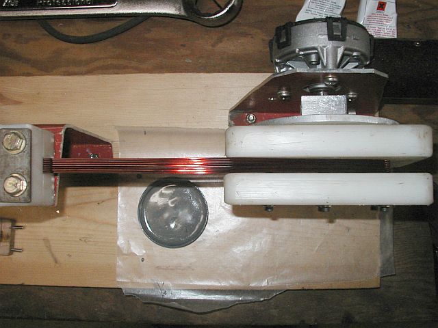
To obtain uniformity and because winding 7x #14 seemed a bit daunting, a winding fixture was needed. Here's what I came up with. It's about 3' long by 9" wide.


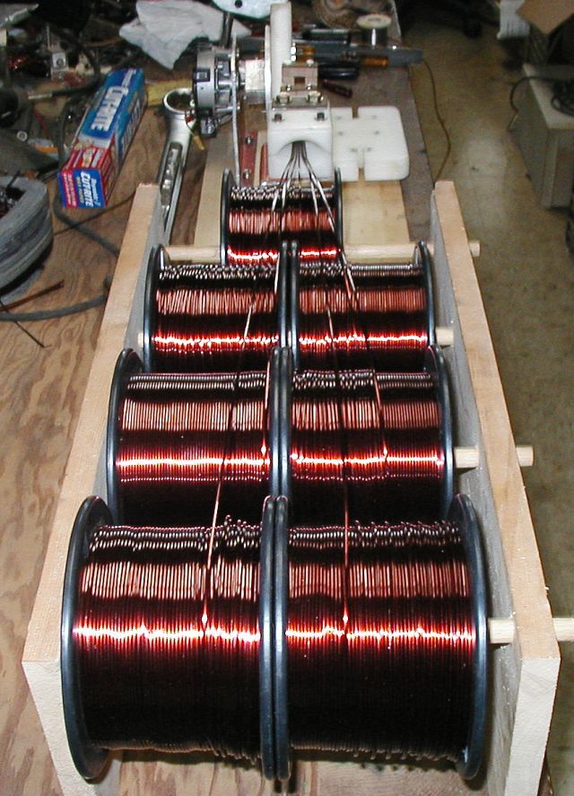
You're looking at over $600 worth of #14 square but not all will be used on this one machine.


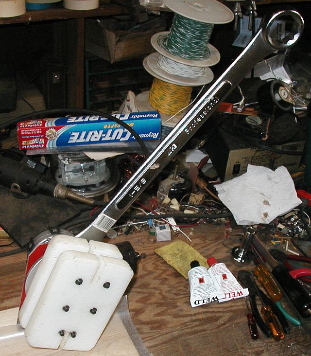
I originally planned to power and automate the winding process but I grossly underestimated the necessary winding tension needed for 7x #14. It became clear on the first test that the 120 watt DC motor, although well geared down, wasn't up to the task of supplying the necessary torque. So, I had to resort to the Armstrong method shown here. Believe me, the long handle is necessary.


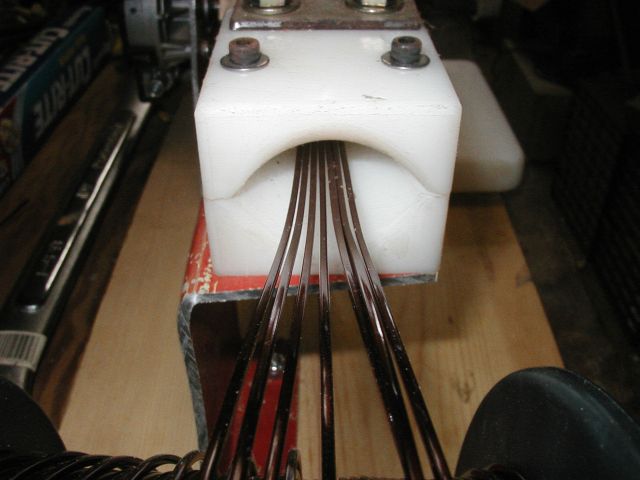
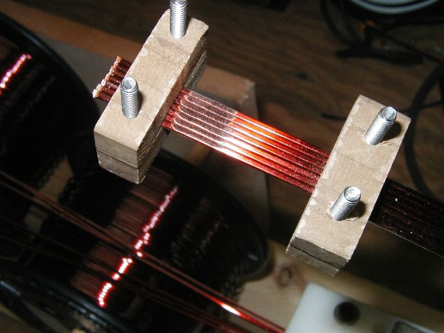
This is the input end of the collimator/tensioner. It's made from two pieces of 0.94" HDPE.


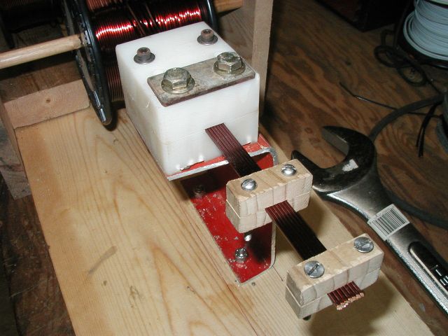
This is the output end of the tensioner. Tension is adjusted by the two large bolts. Also shown are two notched clamps to hold the wire while preparing the end.


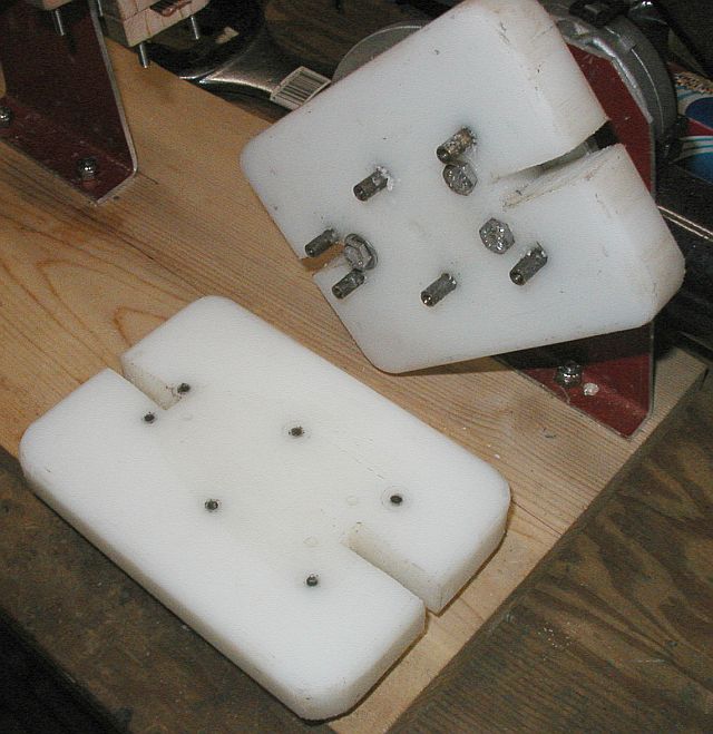
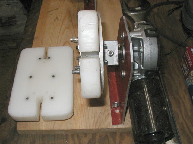
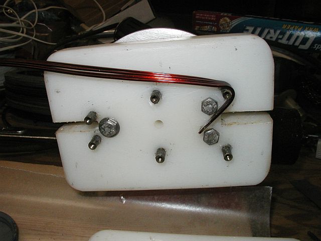
This is the coil mandrel also made from HDPE. The coil corner posts are 0.25" brass threaded standoffs. They are coated with melted candle wax to prevent epoxy from sticking. The fixed half is bolted to an aluminum faceplate, which is on the gearbox shaft. Even though found unsuitable, the motor/gearbox was used unpowered to provide braking torque. Who says a worm drive won't rotate backwards? The slots allow fastening cable ties while assembled if necessary.


The Winding Process

Winding a coil turned out to be pretty time consuming, needing about an hour. Only one per day could be done because of the epoxy cure time


The start end is first prepared by grinding  off insulation with a Dremel tool. It's much easier to prepare this solder joint at this point rather than after completing the coil since it's on the inside.


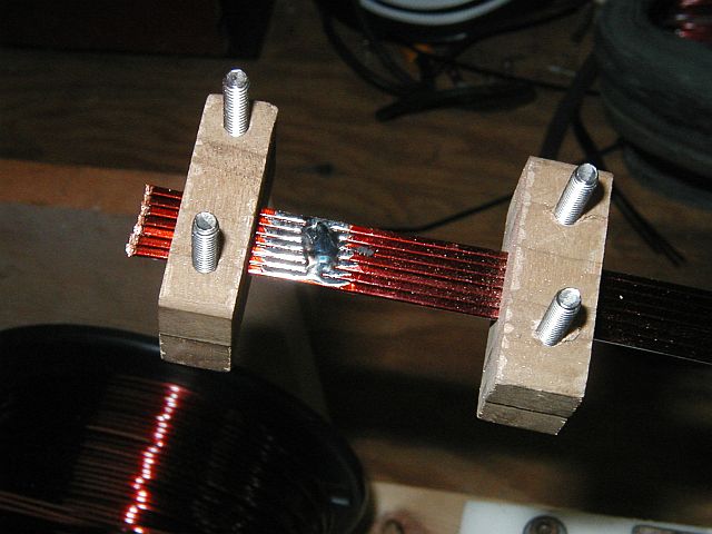
The wire is then tinned and a solder bridge left to keep things together. The wire will then be cut on the left side of the solder area.


The prepared end is bent around the start corner post. It's bent farther than it will end up so that it can hold position under the necessary winding torque. The removable half of the mandrel will now be installed.


We're now ready to get some exercise. The epoxy is mixed, adding a little acetone to thin it for easier application. From here on, the major problem is maintaining adequate and equal tension on the wire. Frequent back-tensioning of individual spools is necessary to equalize them. If  this was to be a production system, I'd certainly find a better way. I have to do only 12.


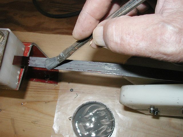
Epoxy is brushed on as we go. It adds substantially to the time since only 6" can be applied at a time. The weight of the handle/wrench plus the gearbox keep it tensioned during the process.


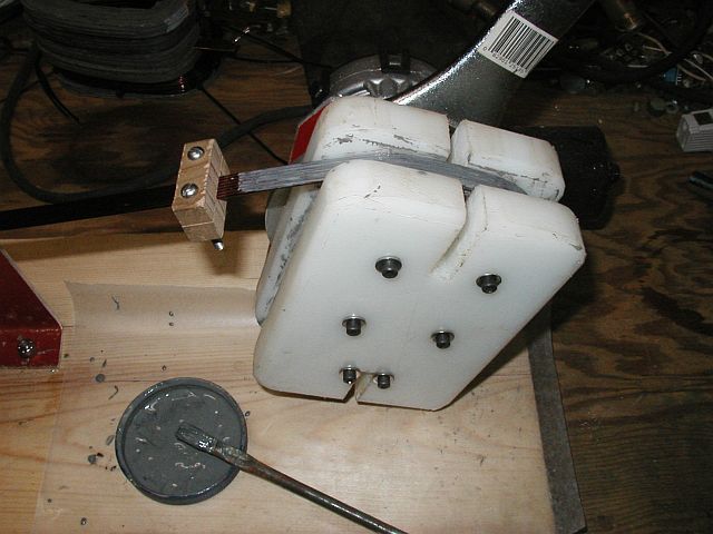
Turns are counted through the mandrel slots. This is the end point. A clamp is installed and the tensioner is tightened right down. Again, the handle weight maintains tension. It's left in this position for 24 hours.


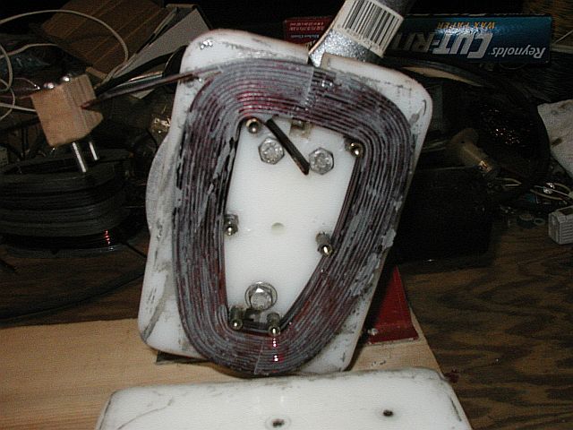
The ready to pop off coil. I'm glad that pretty doesn't count for much. As a precaution, a cable tie will be put around the start and finish (it comes off later).


The Results

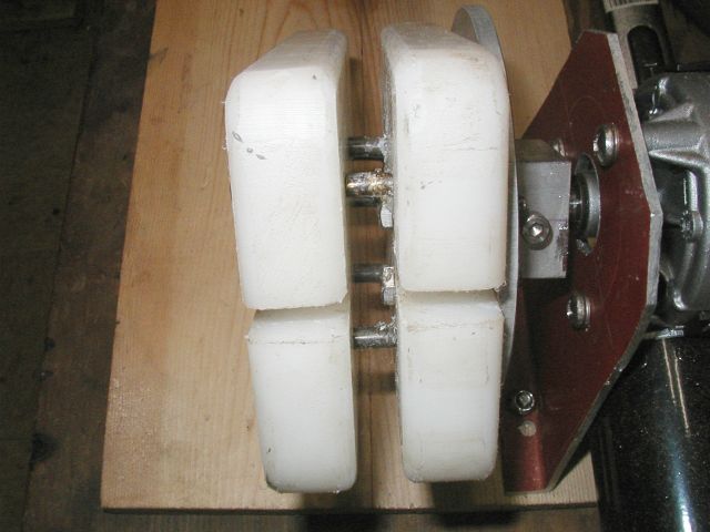
I now have a coil with a near-rectangular cross-section and as dense as I know how to make it. It has a measured resistance of 4.6 milliohms and a measured inductance of 17.5 uH. It's outside dimensions are 4"x6".


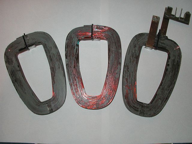
The one on the right has connection links of 0.5"x0.04" copper. The gadget at the upper right is a calibrated shunt for measurement purposes.


Coupling these with a different stator design (no casting) and forced air cooling, I don't expect to burn up a stator.


The next installment will be the stator. Here's a bit of a teaser. The stator mounting plate is 2'x 2'x 0.25" G-10/FR4 FRP. Amazing stuff!


« Last Edit: October 21, 2006, 06:11:10 AM by (unknown) »

WXYZCIENCE

  • Sr. Member
  • ****
  • Posts: 355
Re: A Different Alternator - Part 2
« Reply #1 on: October 21, 2006, 01:29:54 AM »
SamoaPower, from this side it looks like you are in winding heaven. Been up to the same myself. I made 16 and it seems to take forever. You need to make a couple of the plastic looms to speed up the process. I am looking into the square wire myself. Also want to try square aluminum wire for the weight factor. Seven rolls you should have a little left over?


Great pictures and write up. Joseph.
« Last Edit: October 21, 2006, 01:29:54 AM by WXYZCIENCE »

Flux

  • Super Hero Member Plus
  • *******
  • Posts: 6275
Re: A Different Alternator - Part 2
« Reply #2 on: October 21, 2006, 02:29:17 AM »
Wonderful work.


I have difficulty dealing with your T shaped magnets, but I think cut in will be significantly below 100 rpm.


I have never looked at a big design for 12v before, I presume you have good reason to stick to 12v but it really is a nightmare. The alternator alone looks as though it may make nearly 55% at 3kW but with connecting leads and rectifiers you will be well below this.


I am sure your coils will be able to cope with this loss with better cooling.


I am not sure what tsr your prop is, but that looks nearer to a 24v winding to use with a boost converter to me. You may want to connect it 2 parallel 3 phase or 6 phase, but you will have a better idea when you have tried it with the magnet rotors.

Flux

« Last Edit: October 21, 2006, 02:29:17 AM by Flux »

Flux

  • Super Hero Member Plus
  • *******
  • Posts: 6275
Re: A Different Alternator - Part 2
« Reply #3 on: October 21, 2006, 03:04:10 AM »
Joseph, I think you would be advised to avoid aluminium wire, it has many problems.

Flux
« Last Edit: October 21, 2006, 03:04:10 AM by Flux »

zubbly

  • Sr. Member
  • ****
  • Posts: 371
Re: A Different Alternator - Part 2
« Reply #4 on: October 21, 2006, 06:25:44 AM »
hello SamoaPower,


its easy to see you are definately commited to your projects with all this effort you have put into those coils. they would win a beauty contest any time.


your jig for aligning the wires and keeping tention on them reminds me of many of the setups i used to make for xformer winding and coils that needed to be made perfectly layered.


just a tip on the main tensioner: if you use a heavy coil spring over each of the 2 bolts, you can adjust the tention and leave it. the tention setting will last a very long time without having to constantly tighten after a little wear in the tention block.


your stator plate looks very similar to what we called GP-01 in the winding industry. basically a fibre glass plate with incredible strength and wonderfull heat and dielectric qualitys.


thanks for taking the time for all the awsum pictures to share and i greatly look forward to progress on your project.


zubbly

« Last Edit: October 21, 2006, 06:25:44 AM by zubbly »

SamoaPower

  • Sr. Member
  • ****
  • Posts: 417
Re: A Different Alternator - Part 2
« Reply #5 on: October 21, 2006, 07:09:42 AM »
Thanks Flux,

A 'T' doesn't describe the configuration very well. Here's a shot to clarify.


I realize there will be some losses with this but hope the addional magnet material will make up for it. As earlier stated, the target goal is 1kW at 125 rpm. I intend to never let it get over 2kW, more likely a 150 Amp limit.


Yes, well, I debated the system voltage question for a long time. I just have too many 12V loads to justify a switch. Some are high power, like a ham radio amplifier that needs 100 Amps peak at 12V. The myriad of converters starts to become daunting.


I intend to use synchronous rectifiers and will have a loop line resistance of 0.1 Ohm using 3 x 1/0 awg transmission line.


The air rotor TSR is 4.5.


I'm looking forward to the testing phase.

« Last Edit: October 21, 2006, 07:09:42 AM by SamoaPower »

vawtman

  • Hero Member
  • *****
  • Posts: 1425
Re: A Different Alternator - Part 2
« Reply #6 on: October 21, 2006, 07:41:29 AM »
Nice work Samoapower


 Isnt that hdpe fun to work with?


 I think im going coat my exposed coils with the jb.I didnt know you could thin with acetone thats a good idea.


 Wont it be hard to keep all the mags of the same pole that close together?

 Just wondering

« Last Edit: October 21, 2006, 07:41:29 AM by vawtman »

Flux

  • Super Hero Member Plus
  • *******
  • Posts: 6275
Re: A Different Alternator - Part 2
« Reply #7 on: October 21, 2006, 07:43:58 AM »
Yes I thought you must have some compelling reason to stay at 12v.


Your tsr is lower than I thought so your winding will be closer than I first thought.


The line resistance will keep you well out of stall. You will be more than safe at 2kW.


Have you found a simple solution to the synchronous rectifier problem, it looked messy to me with comparators to determine the switching, but at 12v it will be worth the effort.


If you intend to use a boost converter, the later scheme I described seems to be better for 12v, keeping the boost volts within the diode loop seems to give better results. I did a test at 12v to see what happened and it was still perfectly possible without sync rectification.


Look forward to the test results, you certainly deserve credit for the effort. As zubbly mentioned this is more in line with transformer and field coil technology than normal stator winding. Although it may not be worth the effort, you are almost at the point where it would be better to keep each strand as a circuit throughout the winding with the strands transposed so they occupy different places in each coil.


This transposing becomes necessary for large transformers and monster alternators.


Flux

« Last Edit: October 21, 2006, 07:43:58 AM by Flux »

SamoaPower

  • Sr. Member
  • ****
  • Posts: 417
Re: A Different Alternator - Part 2
« Reply #8 on: October 21, 2006, 07:50:27 AM »
Thanks for the kudos zubbly.


A number of improvements to the jig came to mind along the way, but since this was basically a one-shot device, I didn't persue them. I found that tension needed to be adjusted during the wind because of changing winding radius.


Yes, the G-10 FRP plate is really fantastic, albeit expensive ($25/sq ft in 1/4"). It's been around a long time, at least 40 years. I recall using some outdoors for 15 years and was still fine. Don't know why we don't see more used in RE. I think it will make an excellent stator plate with cut-outs for the coils.

« Last Edit: October 21, 2006, 07:50:27 AM by SamoaPower »

SamoaPower

  • Sr. Member
  • ****
  • Posts: 417
Re: A Different Alternator - Part 2
« Reply #9 on: October 21, 2006, 08:28:08 AM »
Hi vawtman,

What I like about HDPE is that I can work it with my woodworking tools, not having a machine shop. Table saw, router etc.


JB even recommends thinning with acetone.


I don't expect a problem with the magnets since they will be retained by a 0.25" thick aluminum disk with cut-outs shaped to the magnet layout. There may be a bit of an issue with getting them in the cut-outs in the first place, but once there, I don't think they will go anywhere.

« Last Edit: October 21, 2006, 08:28:08 AM by SamoaPower »

SamoaPower

  • Sr. Member
  • ****
  • Posts: 417
Re: A Different Alternator - Part 2
« Reply #10 on: October 21, 2006, 09:04:26 AM »
Rotor stall is not really an issue since the rotor is variable pitch. The line resistance wasn't part of the design process for matching, more a necessary evil resulting from limited bucks for copper.


No, I haven't found a simpler approach for synchronous rectifiers than the comparator route, but I guess I didn't consider that way was too messy. Seems pretty straight forward. I have a hybrid version, NIS6111, that allows FET expansion for higher current. I may try those.


Yes, I definately want to explore your latest boost converter design but I think I would still consider replacing the diodes with FETs. Remember, 150 Amps output current needed.


Thanks for the info on transposed strands. Wasn't aware of that.

« Last Edit: October 21, 2006, 09:04:26 AM by SamoaPower »

stephent

  • Sr. Member
  • ****
  • Posts: 268
Re: A Different Alternator - Part 2
« Reply #11 on: October 21, 2006, 10:25:23 AM »
SamoaPower..

Nice work--the coils look nice (pretty strong looking to me and ya can't see that from the ground when installed--ya have to know it's there from the start!).

Might want to chunk a couple of them in the oven set to 180-200F or so for an hour or two to see what 'equalization" may occur when they heat up later, and it wouldn't hurt to do that anyway because of the stiffness of the wire. Seven in hand #14 square musta been a bear to wrap.

Then test the heck out of them setup with the rotors/mags.

Just watch the bending radius for square wire(s), it's not quite as sharp as round can be.

It's looking good, keep us informed.

Lots of thought put into your work.
« Last Edit: October 21, 2006, 10:25:23 AM by stephent »

SamoaPower

  • Sr. Member
  • ****
  • Posts: 417
Re: A Different Alternator - Part 2
« Reply #12 on: October 21, 2006, 02:07:30 PM »
Flux,

I'll ask again a question I put to you recently in your post on the new boost scheme. (probably too far down the list now)


You mentioned that you hoped for improved efficiency from the alternator but that you didn't see it. I also thought an improvement would be in the offing and am curious why you think it didn't materialize.


Was this hope based on more efficient waveform loading? You've often mentioned that the air gap machines don't care for a rectifier load and less power is available than with a resistive load.


Perhaps this is why the Bergey 10kW machine is derated to 7.5kW for battery charging.


It would seem that your boost converter could be used to advantage by running full time, even after main cut-in is reached to load the input waveform during those portions below battery volts. The PWM could be turned off during the time the waveform peak exceeds battery volts.


It would require that the closed loop bandwidth be greater than the alternator frequency but with the high frequency ratio of PWM to alternator, I don't see that as a problem.


What are your thoughts?

« Last Edit: October 21, 2006, 02:07:30 PM by SamoaPower »

willib

  • SuperHero Member
  • ******
  • Posts: 2414
  • Country: us
Re: A Different Alternator - Part 2
« Reply #13 on: October 21, 2006, 11:29:52 PM »
Great pictures

24 hours per coil , ouch , i get impatient when i have to wait an hour for one to cure.

that is a super winder you have made there , nicely done
« Last Edit: October 21, 2006, 11:29:52 PM by willib »
Carpe Ventum (Seize the Wind)

Flux

  • Super Hero Member Plus
  • *******
  • Posts: 6275
Re: A Different Alternator - Part 2
« Reply #14 on: October 22, 2006, 02:29:49 AM »
This is complicated and I am not sure that I have the answers.


I can see your reasoning as the boost converter is the basic element of a high power factor rectifier. In the single phase case there is a large reduction in supply harmonics and that is the reason for its use.


I would expect that prolonging conduction angle would improve copper utilisation as the I^R for a high peak current pulse should be more than for a sinewave.


I looked at a single phase alternator case before, using a choke after the rectifier.


This does maintain continuous conduction and the immediately obvious effect is that it eliminates the severe vibration from a rectified single phase alternator into a battery. Surprisingly I didn't find any improvement in efficiency and it needed a large and costly choke to keep the choke loss low enough to get back to the same efficiency. This is of course with a low frequency choke.


With the 3 phase case and discontinuous conduction in the converter, the effect should be the same with conduction extended over a longer period. The fact that I saw no improvement may be due to the converter loss being higher in discontinuous mode. It seems as though the gain from the copper utilisation in the alternator is a very small factor. The significantly worse performance of alternators with rectifier load may be more complex.


In your 12v case I see the biggest issue being converter efficiency and I think you will benefit from coming off the converter as soon as possible to remove this additional loss. With higher voltages and lower converter loss then there may be a case for keeping in boost longer if it helps the power tracking.


For 12v the better option would be the buck converter, where the alternator volts are always rising and the rate of current rise is reduced, reducing all the I^2R losses as well as tracking the load.


A 3 kW plus converter would be a challenge, but should be possible ( I have done it experimentally up to 1kW). I have never attempted to take the full machine power through a boost converter and that may also be a challenge. I prefer to change over directly to another bridge as soon as it stops boosting. That way a converter failure lets the machine run in normal winds with little effect.


You have committed this winding to boost, but maybe that later you can produce a buck converter and make a new stator with the spare wire.


I really regard the boost converter as a simple option for higher voltage machines.


Flux

« Last Edit: October 22, 2006, 02:29:49 AM by Flux »

SamoaPower

  • Sr. Member
  • ****
  • Posts: 417
Re: A Different Alternator - Part 2
« Reply #15 on: October 22, 2006, 05:15:11 AM »
Know what you mean willib. Lucky I have 14 dozen other projects to keep me occupied.

« Last Edit: October 22, 2006, 05:15:11 AM by SamoaPower »

SamoaPower

  • Sr. Member
  • ****
  • Posts: 417
Re: A Different Alternator - Part 2
« Reply #16 on: October 22, 2006, 05:19:55 AM »
Thanks Flux.

I'm chewing on this.

« Last Edit: October 22, 2006, 05:19:55 AM by SamoaPower »

SparWeb

  • Global Moderator
  • Super Hero Member Plus
  • *****
  • Posts: 5448
  • Country: ca
    • Wind Turbine Project Field Notes
Re: A Different Alternator - Part 2
« Reply #17 on: October 24, 2006, 01:46:20 PM »
Man, you put my coil winder to shame....


But our machines share all the same elements.  I tensioned the wire like yours, two plates clamped together, but I used a piece of fabric to reduce friction.  Tension on the spool was maintained by stacking washers on the spool shaft and then adding a compression spring.  The spring kept all parts in contact with each other, and by tightening a bolt I could tighten the spool.  Nothing would grab or loosen because the washers maintained constant friction as they turn.


Hmmm, never did upload my pictures.  Hope you see what I mean anyway.


A wiper motor would have worked better for my 18 gauge wire.  Sorry it didn't work for you.

« Last Edit: October 24, 2006, 01:46:20 PM by SparWeb »
No one believes the theory except the one who developed it. Everyone believes the experiment except the one who ran it.
System spec: 135w BP multicrystalline panels, Xantrex C40, DIY 10ft (3m) diameter wind turbine, Tri-Star TS60, 800AH x 24V AGM Battery, Xantrex SW4024
www.sparweb.ca

SamoaPower

  • Sr. Member
  • ****
  • Posts: 417
Re: A Different Alternator - Part 2
« Reply #18 on: October 24, 2006, 05:57:29 PM »
Thanks for the comments Steve.


I'm not sure that tensioning the spools is the way to go because as the wire is used and the radius on the spool changes, the tension will change.


I really did underestimate the necessary tension for 7x #14 square. I looked it up, after the fact, and found that 58lb was recommended for single strand. This explains why I need a two foot handle. Wow, 406lb!


I think if I was to do it again, I would use individual adjustable friction tensioners prior to the collimator to equalize the strand tension and the collective device to set the final tension.


Dense coils do come at a price.

« Last Edit: October 24, 2006, 05:57:29 PM by SamoaPower »

SparWeb

  • Global Moderator
  • Super Hero Member Plus
  • *****
  • Posts: 5448
  • Country: ca
    • Wind Turbine Project Field Notes
Re: A Different Alternator - Part 2
« Reply #19 on: October 25, 2006, 01:17:30 PM »
Good points, but I tensioned the spool not to put tension on the coil I was winding, but to prevent the wire from "springing" off a loose spool and becoming a mess.  You could put a small compression spring on the dowels through your spools and some washers to achieve the same effect.  The frction on the spool doesn't have to be significant compared to the coil tension.

For coil tension, maybe a pair of hard rubber rollers with a brake would do?  Rubber rollers can be liberated from old photocopiers.
« Last Edit: October 25, 2006, 01:17:30 PM by SparWeb »
No one believes the theory except the one who developed it. Everyone believes the experiment except the one who ran it.
System spec: 135w BP multicrystalline panels, Xantrex C40, DIY 10ft (3m) diameter wind turbine, Tri-Star TS60, 800AH x 24V AGM Battery, Xantrex SW4024
www.sparweb.ca