Author Topic: Three different DVM's, three different results !#@!  (Read 2095 times)

0 Members and 1 Guest are viewing this topic.

elt

  • Sr. Member
  • ****
  • Posts: 328
Three different DVM's, three different results !#@!
« on: December 15, 2006, 10:25:05 PM »
I'm slowly working on my first mill. Some advice given when I started it was to build the alternator first because it would be easier to match blades to it rather than the other way around... Okay, I've got the alternator put together and I got my two best DVMs out the measure volts and hertz so I could figure out cut-in RPMs.


When I had them both in hertz, the agreed. I put them into AC, they didn't... (They profess "true RMS".) Call the meters "A" and "B"


Hz    A     B


  1.   9.6   8.8
  2.  12.2  11.3
  3.  14.7  13.4


I also got a third meter and read higher than A or B but it didn't claim to be a true RMS meter. I stuck all three into an AC socket and got 120, 117, and 120 volts from A, B and C respectively. A and B differ by 2.5% on the mains but by 10% on the mill. C was accurate on a pure sine wave; makes we wonder what kind of wave my mill is making...


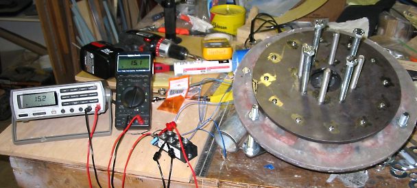
I hooked up a 3-phase rectifier and a 470uF cap. A and B now agree to within a tenth of a volt, better than .1% ... seems like I ought to be able to convert the DC back to RMS but I'm a little fuzzy on the details. Here's a picture of the setup -


By using the hertz readout, I get


  1. Hz, 17.8v DC, (A&B RMS volts were 12.2v and 11.3v)
  2. Hz, 21.9v DC, (A&B RMS volts were 14.7v and 13.4v)


By watching the clock, I get 10.2v RMS, 15.5v DC at 120 RPM with meter A (it's a 12 pole alternator).


The voltage drop across plus and minus on the rectifier is .8v


I can't get the formulas to match up the numbers and I'm wondering if that since there's no load on the cap, that it's charging to a peak to peak value from the rectifier; should I be using a correspondingly lower value as my DC volts?


Besides wanting to know which meter is correct, I'd really like to know my cut-in RPM is for a 24 volt system... as always, I really appreciate the help!


- Ed.

« Last Edit: December 15, 2006, 10:25:05 PM by (unknown) »

drdongle

  • Hero Member
  • *****
  • Posts: 552
different DVM's, different results !#@!
« Reply #1 on: December 15, 2006, 04:42:06 PM »
Keep in mind that digital meters will often read high when the battery is low, so check that you have fresh batterys. I hope that you problem is that simple.
« Last Edit: December 15, 2006, 04:42:06 PM by drdongle »

wdyasq

  • Hero Member
  • *****
  • Posts: 1324
Re: Three different DVM's, three different results
« Reply #2 on: December 15, 2006, 05:20:55 PM »
Most consumer DVMs are setup to read AC volts in the 50-60Hz range. If your HZ is lower (as all wind turbines I have seen or seen discussed here) you are probably not getting good readings.


I'm not sure there is a good way to test the accuracy of a meter without a good regulated source as a standard. But, a small capacitor to kill the DC ripple and measuring that is your best bet, IMO.


Ron

« Last Edit: December 15, 2006, 05:20:55 PM by wdyasq »
"I like the Honey, but kill the bees"

elt

  • Sr. Member
  • ****
  • Posts: 328
Re: different DVM's, different results !#@!
« Reply #3 on: December 15, 2006, 06:40:12 PM »
Thank you, I didn't know that! I'll try fresh batteries in "A"; "B" (which has the lower readings) does have fresh batteries... but I only really see the difference in RMS volts, they both give (more or less) the same readings on DC volts and the diode drop.


- Ed.

« Last Edit: December 15, 2006, 06:40:12 PM by elt »

elt

  • Sr. Member
  • ****
  • Posts: 328
Re: Three different DVM's, three different results
« Reply #4 on: December 15, 2006, 06:55:26 PM »
Thanks Ron,


I can accept that the answer is "D", that none of the meters are accurate as I don't see any factors of the diode drop and square roots of two or three correlating the the DC voltage and the RMS volts.


I still need to figure out the cut-in RPMs and I'm not sure what the DC volts read mean. With the cap in there, I'm concerned that it's reading  peak volts out of  the rectifier and that its a higher number than I should be using to scale RPMs to cut-in voltage.  If that's the case, I've goggled and googled but can't find a factor to convert rectified 3-phase peak to peak volts to RMS volts... I thought I saw something once that was like .9 PTV = RMS but I'm coming up with nothing now.


- Ed.

« Last Edit: December 15, 2006, 06:55:26 PM by elt »

jimovonz

  • Sr. Member
  • ****
  • Posts: 339
Re: Three different DVM's, three different results
« Reply #5 on: December 15, 2006, 07:38:39 PM »
IF you are dealing with a sine wave then the RMS voltage is .707 (1/root(2)) x peak voltge. It depends on the shape of the waveform otherwise.
« Last Edit: December 15, 2006, 07:38:39 PM by jimovonz »

elt

  • Sr. Member
  • ****
  • Posts: 328
Re: Three different DVM's, three different results
« Reply #6 on: December 15, 2006, 08:47:34 PM »
Hi Jim,


I'm not thinking that that's right... I think that .707 is for a single phase rectified; perhaps it's .866 (1/root(3)) for three phase rectified.


Maybe I've been making up a new definition of "cut-in" voltage. I guess that if peak to peak volts is greater than battery volts that the alternator does actually start to charge the battery; just not very much.


In that case, then I guess that cut-in RPM for 25 volts (rectified peak-to-peak) would be


using 21.9v @ 180 rpm = (25+.8)(21.9v+.8)x180 = 205 RPM

using 17.8v @ 150 rpm = 25.8/18.4)x150 = 210 RPM


... about 210 rpm.


I'm still curious about rms charging volts or when the "full power" volts of the alternator kicks in since I'll be using an MPPT boost converter to get what power there is to be had before cut-in... I'm guessing that right at 25 volts where just the peaks from the rectifier would be charging that I'd still be getting more power out of the boost converter.


- Ed

« Last Edit: December 15, 2006, 08:47:34 PM by elt »

jimovonz

  • Sr. Member
  • ****
  • Posts: 339
Re: Three different DVM's, three different results
« Reply #7 on: December 16, 2006, 01:35:44 AM »
If you have all three phases connected to a rectifier (+ cap) then the output is not going to be a sine wave. For any sine wave: Vrms = 0.707 x Vpeak. Cut in is generaly the point at which the alt starts suplying current into the battery so is calculated usng peak voltage (which is what you are measuring with your rectifier + cap). I would go with 210RPM as your cut-in as it is a more direct measurement. Maybe your getting confused with folk who measure Vrms for a single phase so multiply by 1.414 to get the peak phase voltage then multiply by 1.732 (root(3))to get the peak line voltage for a 3 phase star conection.
« Last Edit: December 16, 2006, 01:35:44 AM by jimovonz »

Flux

  • Super Hero Member Plus
  • *******
  • Posts: 6275
Re: Three different DVM's, three different results
« Reply #8 on: December 16, 2006, 02:14:08 AM »
Your speeds with the rectified output are near enough for your cut in speed.


Not a lot of point in worrying about the factor between ac and rectified dc volts because it is waveform dependent. The fact that two meters that claim to be rms don't agree is an indication that at least one is wrong. I have a feeling that the one that reads low on the mains is low everywhere. The difference between the other two is likely to be a waveform problem.


It is likely that the non true rms one is as useful for this as the the other. The cut in voltage is determined by the peak volts and average reading meters scaled rms are as likely to give you a decent answer as the true rms in this case. If you were measuring power into a resistor then the rms unit would be correct.


Anyway, back to the dc. With a sine wave, the mean dc from a 3 phase rectifier is about 1.4 times the rms volts, I have forgotten the exact figure, but it is quite close to the peak value of root 2(1.414).


I wouldn't bother with the capacitor and I would connect a small load on the dc side of the rectifier (100 ohms or so) as the rectifier waveforms totally off load can be strange.


Your battery will see cut in at the peaks of the 6 pulse ripple of the rectified waveform, but the current will be negligible until you reach the mean value. The same will be true of your converter, it may make a few mA during the ripple phase bet nothing serious until you reach the true mean.


This is quite different from the single phase case where cut in will start at peak and move down the waveform as you load it.


If you take the dc mean from the bridge with the small load it includes the diode drops.


Taking your figure at 120 rpm of 15.5v dc that would give a cut in at 24v of

24/15.5 x 120 = 186 rpm. Probably 190 without the capacitor.


The 10.2 vac is a bit low as the waveform tends to be a bit peaky and a true rms voltmeter would read low. The non rms voltmeter may be a bit nearer the 11v that I would expect.


Flux

« Last Edit: December 16, 2006, 02:14:08 AM by Flux »

elt

  • Sr. Member
  • ****
  • Posts: 328
Re: different DVM's, different results !#@!
« Reply #9 on: December 16, 2006, 08:11:13 AM »
 

I read 1.2 volts per cell in the alkaline energizers in meter "A"; that's a good amount of use but still above the power knee for them. Still, I put in fresh batteries and got the same results. Good idea, I wish that had been it!


- Ed.

« Last Edit: December 16, 2006, 08:11:13 AM by elt »

DanG

  • Hero Member
  • *****
  • Posts: 1124
  • Country: us
  • 35 miles east of Lake Okeechobee
Re: Three different DVM's, three different results
« Reply #10 on: December 16, 2006, 09:53:08 AM »
My first DVM had flaky readings until I discarded the cheap test leads it came with and permanently soldered Fluke VOM meter leads directly to the circuit board. if you do this put a strong stress-relief nylon tywrap in to keep from pulling traces off PCB if you ever drop unit and catch its fall by the test leads...  I also have a solder glob near end of the brass test probes so that I can 'solder tack' a jumper wire into a circuit onto the probe to make sure I get valid connection when needed; the extra wire is removed when not in use. The meter is now over 22 years old and still going strong but isn't much to look at anymore...
« Last Edit: December 16, 2006, 09:53:08 AM by DanG »

Dennisd

  • Newbie
  • *
  • Posts: 26
Re: Three different DVM's, three different results
« Reply #11 on: December 16, 2006, 11:14:32 AM »
Some things that affect accuracy of DVM's, one meters input may be filtered to get rid of harmonics, which are probably present with hand made coils. the other is that the the accuracy is only as good as the initial calibration. Find someone who has had their meter recently calibrated, and compare yours (electronic repair shops might let you compare yous to theirs}. At work, we are required to send our test  equipment out for calibration once a year, so I just bring my meter to work and compare the results. As for 1 phase vs 3 phase, a capacitor will bring both up to peak voltage, so a discharge resistor is required to see the difference. the ripple voltage is the big difference. with 1 phase the voltage has 180 degrees to decay, 3 phase has only 60 degrees. Have you considered getting a battery, and just measuring when current starts to flow?

Dennis    
« Last Edit: December 16, 2006, 11:14:32 AM by Dennisd »

elt

  • Sr. Member
  • ****
  • Posts: 328
Re: Three different DVM's, three different results
« Reply #12 on: December 18, 2006, 08:24:23 PM »
Have you considered getting a battery, and just measuring when current starts to flow?


Well, that makes sense... I feel kind of stupid not thinking of that!


- Ed.

« Last Edit: December 18, 2006, 08:24:23 PM by elt »