Actually it's not my first windmill, I have built several toy windmills as a child and also occasionally attached small PM DC motors to them to watch the voltmeter dance during gales.
Nevertheless this is the first one with some theoretical background involved and variety of wood and metal work skills put to use. The goal of this project is getting familiar with the workings of a power generation windmill and to make most of the mistakes before scaling everything up. Therefore as efficiency of the mill is not crucial I opted for the first choice every beginner would - using a car alternator, thereby making this story a practical walk through of such a poor choice for all the newbies.
So let's see what's the best we can get out of this - here goes nothing ...
First thoughts ...
First thoughts considered putting the windmill rotor shaft on some durable bearings and then gearing up the alternator with bicycle gearwheels and chain or something similar depending what I would have come across and building everything else from there. This would suggest quite a large blade diameter to harvest enough energy hoping to gear up the rotation but since I didn't want things to get too large for now and had only 100x50 mm studding laying around I maid rather ignorant decision to start with 1,5m diameter blades.
Oh, by the way, as I have to cope with all the English units everywhere I will bless you all with my metric ones this time ... (grin!)
Blades
So as the first thing I started graving out the blades. Sadly I didn't took any pictures of the process but it looked the same as in all the tutorials on the web and in books anyway. Although here's a picture of me posing with the finished rotor.
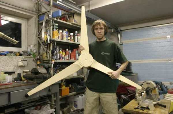
Making the blades went really fast. First I used formulas from the Piggotts book "Windpower Workshop" to calculate everything needed and then spent half of a day and another evening making one blade. It turned out though that wood work with such a precise shape in such a small scale is quite tricky so I turned to Otherpower's design suggesting using only strait lines form tip to root. Ii took then one day to make all three new blades. Electric planer speeded things really up.
Alternator
Then on one evening I walked to the nearest junkyard and got myself an Opel Rekord's alternator from year 83'. Costed me 300 EEK (about $25) and looked like it had fallen off by itself, not taken off (horrible!). Well it was the cheapest working one.
It's a Bosch brand rated for 14V, 45A. After little cleaning I started making some tests spinning it around with hand drill.
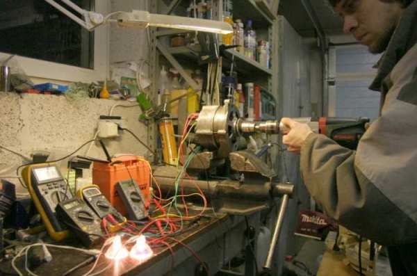
I used several different wattage 12V halogen bulbs to load the alternator and measured field coil current, output current, voltage and frequency to calculate RPM. The battery was used to excite the field coil before the alternator was producing enough current by itself.
Now about the main concerns regarding car alternators.
The voltage regulator is not suitable in wind power. True of course. But I was thinking, if I use shunt regulator keeping the voltage a little under the rated voltage of the alternator's regulator it wouldn't kick in during normal operation but would still be there to protect the alternator from burning out itself if other controls fail. Not surprisingly bad idea still! I think it depends on the type of the regulator but I didn't realise how suddenly it cuts off the load. Hench if just a little inaccuracy in other controls let the voltage to rise over 14V just for once the voltage regulator would cut off field current leading to unstoppable runaway. Fortunately it's easy to by-bass the regulator.
Then the field coil needs exiting when the alternator has gathered enough speed. Not very hard to devise such a system but it still eats up all your power in low winds just to keep the darn thing exited. I think it would be all the better replacing the field coil with microwave oven magnets - and I'm planning to do just that.
Finally the worst part - high RPM required. Well it doesn't seems so bad at all in my case. Regrettably I didn't made any exact notes during the testing because I wasn't really sure of anything, just wanted to get a overall picture but I will make some more tests soon and keep you posted. Still I noticed that the RPMs didn't rise to hight instead torque started to increase with the load. Maybe it's that the alternator is from a car old enough that doesn't know such high RPMs so the alternator must be a little bit better just to get something out of it.
Now looking at a spreadsheet showing RPMs and power for my blades at a given wind speed things look quite fair. Assuming no gearing cut-in speed would be somewhere at 7 m/s and getting up to 100W in winds 10 m/s seems fair enough for such a small mill that's not even meant to produce real power.
Construction of the windmill
So I discarded the idea of gearing and started building.
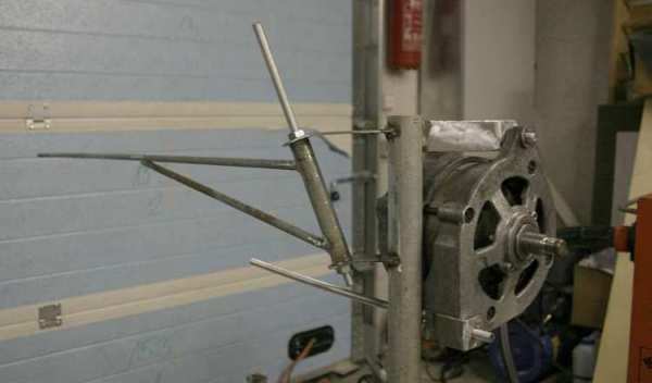
Not much to say here, it's Piggot's furling tail design. Rotor center is ~80mm off from the yaw axis and the tail hinge is aligned at about 20 degrees and 45 degrees away from the rotor axis. Tail stops and yaw bearing are jet to be added.
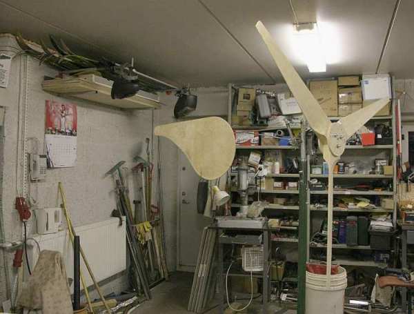
And here it's all put together. Let's take a closer look on it on next pictures.
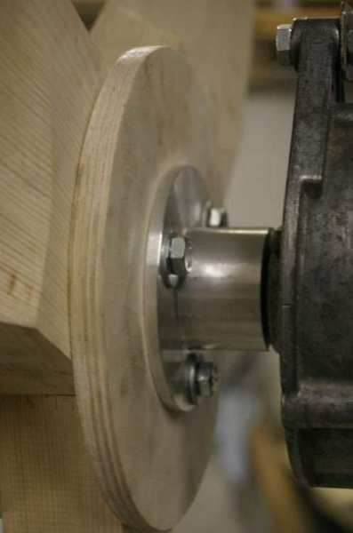
This is how the rotor is mounted on the alternator shaft. The flange is machined out of aluminium. The shaft is threaded and a nut fits inside the flange. Then the rotor is simply bolted on. I don't know if the alternator bearings would hold up, time will tell ...
In the mean while I managed to paint the thing.
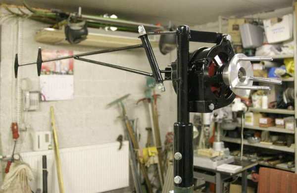
You can see stops for the tail added. The yaw "bearing" is made of different sized pipes. First a PVC pipe is precisely fitted inside the outer steel pipe so it stays put because steel pipes are quite rough inside. Then a smaller steel pipe which is welded on the fat mounting pipe is greased and fitted inside the PVC one. This gives nice free and smooth movement without slacks. I don't think the PVC pipe wears out faster than any other moving part.
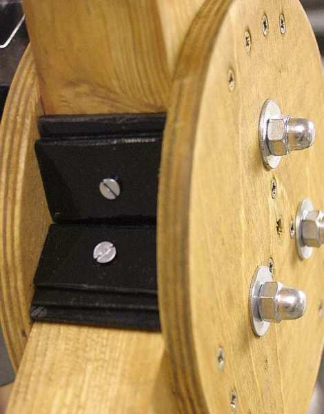
Blades are balanced with those pieces of steel screwed to the rotor. And the whole thing is finished on following pictures.
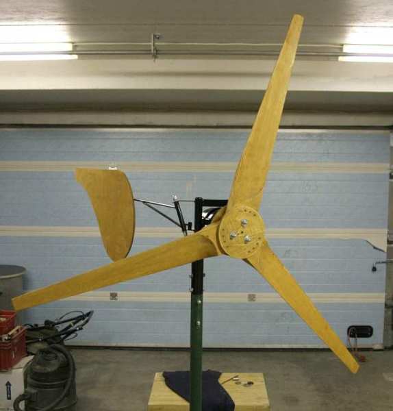
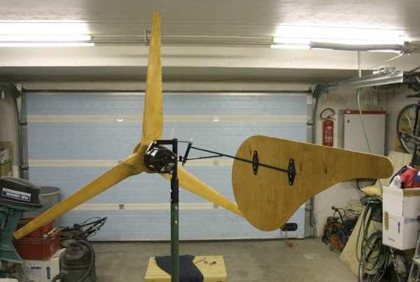
I took two full days all together to build all this. After that it was finally time for some test flight!
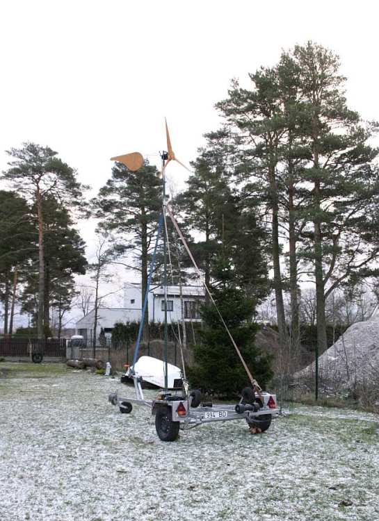
Ehmmm ... yes, that is a boat trailer! I think one can really see the anticipation to get the mill up.  The trailer is wide an heavy enough for not dipping over and the winch was already in place, I only removed one of the bottom rollers and mounted my tower - what a great portable tilt-up tower!
The mill was up and flying in an hour and I measured some 300-400 RPM and 6-8V into 0,5W load in a light breeze with the field coil powered by battery.
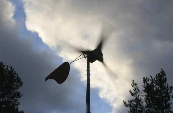
As of 21.02.2006 the mill is up in the backyard free running just for amusement since there's hardly any wind to do anything useful. Just as someone has stated somewhere: there's a total calm for several weeks after you have gotten up you first mill!
What's next
Of course things are long way from finished. There's no load control whatsoever although I'm working on it at the moment and those 6-8V into 0,5W ain't getting us nowhere so the alternator is up for modification to PM alternator and maybe some rewinding. I'll keep you posted!
Also there's some more larger size pictures over here kuu.pri.ee/pub/tuulikud .