Author Topic: 5.125" dual rotor test.  (Read 4204 times)

0 Members and 1 Guest are viewing this topic.

Jerry

  • Hero Member
  • *****
  • Posts: 1519
5.125" dual rotor test.
« on: February 25, 2007, 05:04:26 AM »
This is the beginning of followup on last years debate. It was sugjested that I make an evaluation of these diferant 3 phase wire scheems with a prime driver.


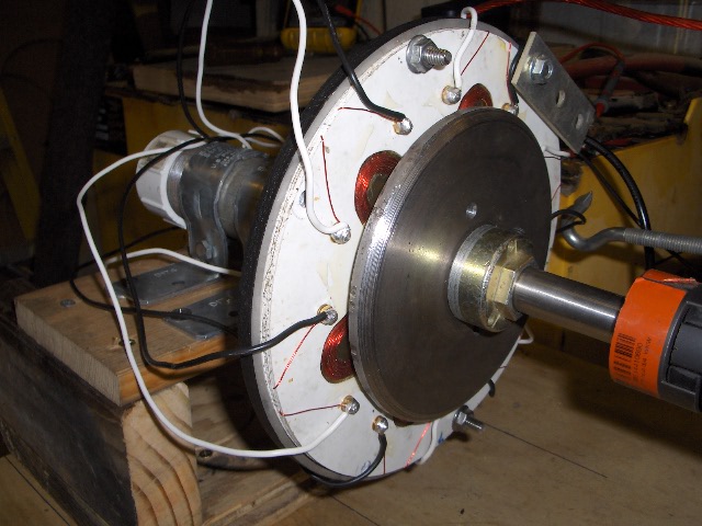
This is a PMA dual rotor alt driven by a motor. The test will determin wich wireing scheem is more eficient.


It is my contention that star is least eficient. I did present some test that indicated this but still the idea was not accepted by most.


The sugjestion was made that I should compair the requiered drive power of both to see witch scheem made the best use of driven power, wire oz. for oz. and magnets.


I've been building several test alts. Last years tests included a car alt, small dual rotor disc alt and 2 types of motor conversions. They all had very simular results as I've found in todays test.


Todays test alt is a 5.125" dual rotor disc alt. each disc has 8 each 1"X1/2"X.25" Neos.


The gap between magnets is about 3/8". The stator thickness is about .25".


2 indentical stators were cut from 1/16" thick fiberglass shower stall material.


All wafers for the 2 stators were cut at once this included the holes for coil placement. The atempt here was to make these 2 stators as identical as posable.


This icluded coil size, shape and posistion.


The star stator has 6 coils wound with 40 turns of # 18 gage wire.


The "Jerry Rigged" stator was wound with 150 turns of 24 gage wire. This stator was actully wound first. I found that 150 turns of 24 gage fit the aloted coil space very tightly. Thats what I wanted a snug fit so the coils were held in proper alignment.


Next I wound the star coils with 18 gage. The therory was to wind the star coils with 1/4th the turn count as "Jerry Rigged".  As it turned out there was enough room for 40 turns allthough 37.5 turns would have been 1/4th of the "Jerry Rigged" 150 turns. Last year it was sugested that star needed a few extra turns to make up for its out of phase voltage loss. So I was happy to get star the 10 extra turns.


In star there are at any given instant 4 coils connected in sires. I wanted each "Jerry Rigged" coil to equal the entier turn count of the 4 star siresed coils.


This ment that the "Jerry Rigged" wire would have to be 1/4th the circular mills.


18 gage and 24 gage was a good match for this project.


The star stator is wired in the accepted scheem. "Jerry Rigged" is wired with 6 fullwave bridge rectifiers, 1 bridges per coil and all there dc outputs are perelelled.


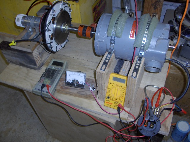
I used a GE dc compound wound motor as the prime driver. A 100 volt dc power supply was connect to this motor. The power supply was connected to a 5KW Variac.


This alowed a voltage of 0 to 100 volts dc for the prime driver motor. The driver motor was coupled to the small dual rotor disc alt via Love Joy coupler. A direct conection.


Voltage and amperage were monitored going into the prime driver motor and voltage and amperage were monitored comming out of the dual rotor disc alt. 4 meters at once.


Open volts, loads volt, load amps were recorded for both stators and drive motor during test.


I hope to expand further testing soon to include rpms at diferant loads, temperatures after a set time and stress load to compair the 2 scheems. It is my belife star will run conciderably hotter the "Jerry Rigged". I also belive this acounts for so many burnt stators and coils.


Here are todays test #s.


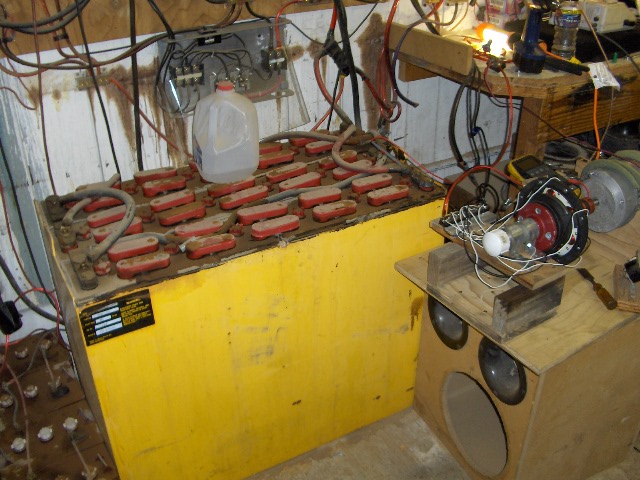
The load is a 2850 LB lift truck battery configured for 12 volts. Beging test with battery at 12.62 volts at rest.


I ran the Variac up to 100 volts, at this drive motor voltage star produced 14.4 volts open no load.


Same test for "Jerry Rigged" , drive motor at 100 volts "Jerry Rigged" open no load volts 17 vdc.


Next I connected star to the big battery load. Again in star with the driver motor at 100.31 volts and 6.4 amps star was produceing 1.7 amps at 12.72 volts.


For star the means it was requiering (100.31 v X 6.4 amps) 641.98 watts of driveing power while produceing (1.7 amps X 12.72 volts) 21.624 watts.


I remove the star stator and replaced it with the "Jerry rigged stator. Gap was maintained and stator posistioning was exactly the same. The speaker basket stator support mandated this.


Same test. I drove the "Jerry Rigged" Stator up to the exact same 1.7 amps that star was producing and the same 12.72 battery volts. The diferance was at this point the prime driver motor was operating at 5.2 amps at 90.5 amps for 470.6 watts of drive power requiered.


So to produce 21.624 watts output star requiered 641.98 watts while "Jerry Rigged" requiered 470.60 watts to produce the same power. Thats a diferance of 171.35 more drive watts requiered by star.


Next I drove the prime drive motor up to 100.39 volts at 6.4 amps or 642.496 drive watts. At this drive power star was produceing 21.624 watts.


"Jerry Rigged at this prime driver motor power "Jerry Rigged" was produceing 12.74 volts at 2.8 amps for 35.56 watts.


This littel alt is very tiny. I'm going to load it down heavyer at 6 volt and maybe even 2 volt battery to thest the thermal condition.


However I belive these results are scaleable and I intend to dso just that.


I'm working on (as time permits) a 4 ft Hugh Piggot alt with the same tests. Also a 12/9 wedge alt and a 1.5" disc magnet test alt.


I'm convinced the results will be the same. I'll be testing rectangular, round and wedge magnets as well same shapes for coils.


Heres a few pictures of the test set up.


                             JK TAS Jerry

« Last Edit: February 25, 2007, 05:04:26 AM by (unknown) »

willib

  • SuperHero Member
  • ******
  • Posts: 2414
  • Country: us
Re: 5.125" dual rotor test.
« Reply #1 on: February 24, 2007, 11:01:16 PM »
jerry in that last photo , what is that big yellow thing with the milk jug on it?

havnt finished reading your post yet , just had to ask?
« Last Edit: February 24, 2007, 11:01:16 PM by willib »
Carpe Ventum (Seize the Wind)

ghurd

  • Super Hero Member Plus
  • *******
  • Posts: 8059
Re: 5.125" dual rotor test.
« Reply #2 on: February 24, 2007, 11:45:24 PM »
Nice write up.


I knew the numbers would be like that if I could feel the difference with a hand drill!

G-

« Last Edit: February 24, 2007, 11:45:24 PM by ghurd »
www.ghurd.info<<<-----Information on my Controller

coldspot

  • Hero Member
  • *****
  • Posts: 843
  • Country: us
Re: 5.125" dual rotor test.
« Reply #3 on: February 25, 2007, 12:05:13 AM »
jerry-

As I have posted in the past,

I think your onto something with your

"jerry phase"

just thinking it thru tells me that and I do belive that your testing will also show it!


Great work and nice write up!

Thanks

:)


PS: Helping the star with extra wire isn't real world "straight up" comparison or testing.

Delta Vs Star Vs Jerry Phase

Same turns

Same Wire size

Same magnets

Same Gap

Same load


"Jerry Phase"

Will be the "Big Dog" in the end!!!!!

I'm sure of it!

« Last Edit: February 25, 2007, 12:05:13 AM by coldspot »
$0.02

Flux

  • Super Hero Member Plus
  • *******
  • Posts: 6275
Re: 5.125" dual rotor test.
« Reply #4 on: February 25, 2007, 01:23:26 AM »
Nice work jerry. Any chance of a scope picture of the waveform with the star connection on no load.


  1.  scope on star point to one line.
  2. scope on 2 lines.


It would be useful if you were to do these on all the examples you test. I know it is early in your testing and you may have intended to do this anyway.


Keep up the good work.


Flux

« Last Edit: February 25, 2007, 01:23:26 AM by Flux »

Chagrin

  • Full Member
  • ***
  • Posts: 195
Re: 5.125" dual rotor test.
« Reply #5 on: February 25, 2007, 01:35:40 AM »
"The load is a 2850 LB lift truck battery configured for 12 volts."

« Last Edit: February 25, 2007, 01:35:40 AM by Chagrin »

fungus

  • Sr. Member
  • ****
  • Posts: 448
Re: 5.125" dual rotor test.
« Reply #6 on: February 25, 2007, 04:54:28 AM »
Pretty nice tests. Do you have any readings of rpm while doing the various tests?

« Last Edit: February 25, 2007, 04:54:28 AM by fungus »

tecker

  • SuperHero Member
  • ******
  • Posts: 2183
Re: 5.125" dual rotor test.
« Reply #7 on: February 25, 2007, 06:22:38 AM »
Rpm would be nice or frequency of one coil . I think that a dab of resistance on each coil  effects the time constant of the coil = added back emf = increased voltage rise .At lower rpm? . The bridge and maybe a little component matching who knows? If it all pans out we could calculate a good combo for low rpm .

The added resistance  affects the stator also but once stared some of the back emf is shunted internal to the stator and just produces heat .
« Last Edit: February 25, 2007, 06:22:38 AM by tecker »

tecker

  • SuperHero Member
  • ******
  • Posts: 2183
Re: 5.125" dual rotor test.
« Reply #8 on: February 25, 2007, 06:36:34 AM »
I remember a report you gave on the proformance for your 8" rotor . How it ran cool under some high wind . Would it not be fine to be able to cool the stator operation by controlling and useing the back emf. Yes sir I think this will work
« Last Edit: February 25, 2007, 06:36:34 AM by tecker »

TomW

  • Super Hero Member Plus
  • *******
  • Posts: 5130
  • Country: us
Re: 5.125" dual rotor test.
« Reply #9 on: February 25, 2007, 08:03:59 AM »
Willi;


jerry in that last photo , what is that big yellow thing with the milk jug on it?

havnt finished reading your post yet , just had to ask?


My guess is fork truck battery or it sure looks like one.


Cheers.


TomW

« Last Edit: February 25, 2007, 08:03:59 AM by TomW »

willib

  • SuperHero Member
  • ******
  • Posts: 2414
  • Country: us
Re: 5.125" dual rotor test.
« Reply #10 on: February 25, 2007, 08:40:15 AM »
:)

i just finished the post this morning, wow

thats one big ass battery !
« Last Edit: February 25, 2007, 08:40:15 AM by willib »
Carpe Ventum (Seize the Wind)

electrondady1

  • SuperHero Member
  • ******
  • Posts: 3120
  • Country: ca
Re: 5.125" dual rotor test.
« Reply #11 on: February 25, 2007, 08:58:59 AM »
real science jerry thanks,

 perhaps a temperature comparison could be made.
« Last Edit: February 25, 2007, 08:58:59 AM by electrondady1 »

scottsAI

  • Hero Member
  • *****
  • Posts: 884
Re: 5.125" dual rotor test.
« Reply #12 on: February 25, 2007, 11:56:51 AM »
Hello Jerry,


Nice work.

Your interpretation for what is presented is OK. The conclusions is not. Sorry, but this is why your posting so someone can explain it. I will try.


We all know the output voltage of a PMA is directly proportional to RPM.

Under the same conditions the output voltage of Y is 1.73 times higher than delta.

In the power industry, if one was even a little more efficient it would dominate the market, as it is, delta and Y are both used. I have verified this personally, Under AC conditions they are the same efficiency. Notice I stated AC conditions.


Now for your testing, why the difference? Ok, not easy, goes back to some posts about matching the generator to the load. Same here.


The battery as a load is seen by the generator as a "voltage dependent resistive load". What does that mean? The Load (battery) has high resistance (as seen by the generator) until the generators output voltage exceeds the batteries voltage. Of course! Current in the generator and Battery are the same.

Once generator's output is above the battery's, the current flowing will be based on the generators output resistance. I = (Vgen - Vbat) / Rgen

Expect actual battery internal series resistance to be more than 100x lower, therefore ignored to simplify this explanation.

Apparent Battery load resistance is Rbat = Vbat / I


Earlier we stated the Y output voltage is 1.73 times higher.

The Y generator's impedance is also 1.73 times higher


The same generator configured as Y gen with the same load current as when a delta maintained into the fixed voltage load will be a less efficient system! Guaranteed.


Does that mean we should all use delta? NO.

Please tell me why:-? (Has to do with RPM)

Have fun,

Scott.

« Last Edit: February 25, 2007, 11:56:51 AM by scottsAI »

TomW

  • Super Hero Member Plus
  • *******
  • Posts: 5130
  • Country: us
Re: 5.125" dual rotor test.
« Reply #13 on: February 25, 2007, 12:22:42 PM »
Scott;


Not trying to disagree, but.....


I, personally, Do Not think you can draw a parallel between 3 phase AC grid power and 3 phase turbine power. For several reasons.


Not willing to spend much time explaining why I think this because regardless of what I say someone will twist the meaning into something I did not state.


Just think about it for a few minutes and look at the circulating currents in a turbine regardless of which 3 wire method is used.


I suspect folks mostly landed on using 3 phase for less vibration and 3 wires down the tower [both good] than any true power production advantages.


Maybe it is me but I just don't see the advantage otherwise.


Just an opinion.


Cheers.


TomW

« Last Edit: February 25, 2007, 12:22:42 PM by TomW »

tecker

  • SuperHero Member
  • ******
  • Posts: 2183
Re: 5.125" dual rotor test.
« Reply #14 on: February 25, 2007, 01:07:44 PM »
I think that's it three ac wires down the pole is the main reason . Good power and rugged . Not so likely to get hammered by lightening . Components at the  of the tower is a big maintenance issue .
« Last Edit: February 25, 2007, 01:07:44 PM by tecker »

tecker

  • SuperHero Member
  • ******
  • Posts: 2183
Re: 5.125" dual rotor test.
« Reply #15 on: February 25, 2007, 01:08:49 PM »
That's top of the tower
« Last Edit: February 25, 2007, 01:08:49 PM by tecker »

scottsAI

  • Hero Member
  • *****
  • Posts: 884
Re: 5.125" dual rotor test.
« Reply #16 on: February 25, 2007, 02:18:13 PM »
Hello TomW,


Not a problem TomW.

First we have to agree ohms law works. Yes.

The whole idea of the math is to express things in simple terms.

Three phase power whether grid or tower generated does NOT mater.


Using RMS AC voltages and DC battery voltages with a rectifier and a nonlinear load is not technically correct, in general terms it is, I did not resort to instantaneous voltages and currents. Just did not feel it would be understood or appreciated. If you like I can?


Yes, normal assumptions do not work here due to the very non linear nature of the battery as a load. Also where I believe most of the confusion is created.


I do not have a problem if you don't believe me, would rather you figure it out for yourself.

But, I am always willing to learn, would like to know where I was wrong...

Just like you, telling me it doe not work, does not help me or anybody else understand here.


Jerry thinks he is on to something, I just explained he is not. Even with his great work.

If the output voltage is designed to be the same for the Y or delta generator based on a given RPM then the efficiency will be exactly the same all else the same. (require different wire thickness and number of turns, same amount of copper)


Configuring it Y or Delta as a kiss of death to Y because it's less efficient is wrong.

I have noticed people here will do strange things thinking they are improving efficiency, when it is either wrong or much less beneficial than they think. Good example is the number of blades.

Looking around the web, some papers claim 4 blades harvest 4% more power than three...


I have operated power plants, done a lot of math with 3 phase power, not recently, took me a while to do my write up. Attempting to make it easily understood, simple and correct.

Thanks for your thoughts.


Willing to learn/teach,

Scott.

« Last Edit: February 25, 2007, 02:18:13 PM by scottsAI »

tecker

  • SuperHero Member
  • ******
  • Posts: 2183
Re: 5.125" dual rotor test.
« Reply #17 on: February 25, 2007, 03:22:34 PM »
Just as a matter of fact the y delta is not up for test . Testing y was done as a comparison to

Three phase to individual coils rectified .
« Last Edit: February 25, 2007, 03:22:34 PM by tecker »

tecker

  • SuperHero Member
  • ******
  • Posts: 2183
Re: 5.125" dual rotor test.
« Reply #18 on: February 25, 2007, 03:35:13 PM »
He never showed delta under test .
« Last Edit: February 25, 2007, 03:35:13 PM by tecker »

scottsAI

  • Hero Member
  • *****
  • Posts: 884
Re: 5.125" dual rotor test.
« Reply #19 on: February 25, 2007, 04:19:32 PM »
Hello tecker,


Thanks, yes your right, Good point, I simplified the Three phase to individual coils rectified to calling it Delta, which was easier, I should have made that point, thanks.


The generators impedance should be less with delta vs Three phase to individual coils rectified , but that contradicts testing Jerry has done. The difference did interest me, but not enough to find the time to figure it out!


At work I'm in the process of getting a high end simulator ($5K). Maybe I will draw it up as a test and see what we will see!

Have fun,

Scott.

« Last Edit: February 25, 2007, 04:19:32 PM by scottsAI »

tecker

  • SuperHero Member
  • ******
  • Posts: 2183
Re: 5.125" dual rotor test.
« Reply #20 on: February 25, 2007, 04:42:51 PM »
AC down the pole will be a trick but If the single phase - single coil is going to keep it in the range for platic you goto like it .  
« Last Edit: February 25, 2007, 04:42:51 PM by tecker »

tecker

  • SuperHero Member
  • ******
  • Posts: 2183
Re: 5.125" dual rotor test.
« Reply #21 on: February 25, 2007, 04:44:18 PM »
 that's temp range for plastic sorry
« Last Edit: February 25, 2007, 04:44:18 PM by tecker »

scottsAI

  • Hero Member
  • *****
  • Posts: 884
Re: 5.125" dual rotor test.
« Reply #22 on: February 25, 2007, 05:00:51 PM »
I am sorry, but I have no idea what you just said, even with the correction?

Scott.
« Last Edit: February 25, 2007, 05:00:51 PM by scottsAI »

tecker

  • SuperHero Member
  • ******
  • Posts: 2183
Re: 5.125" dual rotor test.
« Reply #23 on: February 25, 2007, 05:11:54 PM »
 Rectifing single phase off the stator and sending it 50 to 100 ft is doable but not as good as getting Ac in the range of 15 to 30 volts down to your load .But if this keeps the temprature in the range for most plastics ? I like it  
« Last Edit: February 25, 2007, 05:11:54 PM by tecker »

RP

  • Hero Member
  • *****
  • Posts: 722
  • A dog with novelty teeth. What could go wrong?
Re: 5.125" dual rotor test.
« Reply #24 on: February 25, 2007, 06:08:25 PM »
" "Jerry Rigged" is wired with 6 fullwave bridge rectifiers, 1 bridges per coil and all there dc outputs are perelelled."


Jerry, did you mean that Jerry rigged is with outputs in series?  I thought your concern about star connection was the voltage produced and that the multiple recitifers were to be in series.

« Last Edit: February 25, 2007, 06:08:25 PM by RP »

zubbly

  • Sr. Member
  • ****
  • Posts: 371
Re: 5.125" dual rotor test.
« Reply #25 on: February 25, 2007, 06:16:38 PM »
hi Jerry,


i always wanted the chance to try out a little different connection on the dual rotor gens. if you have the time and are willing to try it out just to see what the effect is on the final voltage output. i would appreciate it if you could find the time to try it.


basically, connect the jumper between the two coils of each phase as you normaly would. then connect the finish of phase C to the jumper of phase A, the finish of phase A to the jumper of phase B, and the finish of phase B to the jumper of phase C. check your voltage output of all 3 phases compared to the original star or delta connection.


again, only if you have time to try it.


zubbly

« Last Edit: February 25, 2007, 06:16:38 PM by zubbly »

stephent

  • Sr. Member
  • ****
  • Posts: 268
Re: 5.125" dual rotor test.
« Reply #26 on: February 25, 2007, 07:24:57 PM »
So why use 6 Jerry coils instead of just 3 (3 jerry coils would equal 6 star coils??) for comparison?

I'm just trying to get a handle on the leveling of the playing feild, and I am a bit confused.
« Last Edit: February 25, 2007, 07:24:57 PM by stephent »

DanB

  • Global Moderator
  • SuperHero Member
  • *****
  • Posts: 2151
  • Country: us
    • otherpower.com
Re: 5.125" dual rotor test.
« Reply #27 on: February 25, 2007, 08:51:38 PM »
Firstly - damned fine work Jerry and I know you're not done with it yet...

And I expect by this time you think me hard headed and a skeptic in general(I know I am)


But I do tend to agree with Scott here.  It really should be about the same in my understanding - right now Im not quite up for trying to write down why as I see it.


But I think the test is a bit off in this:  to get a good comparison under your current testing scheme both alternators must be producing the same open voltage at the same rpm, the magnet rotors and airgaps must be the same,  and the coils must all be teh same size and weight.  I think you got the size and weight right, and the stators are being tested under identical conditions, but rpm vs open voltage Im not sure about.  


I can also see about what flux suggested.. certain wave forms might favor 'jerry rigged' or delta.  (as I see it Jerry Rigged and delta are really the same except that jerry rigged assures there will be no parasitic currents running around between coils within the same phase).  


You've just about inspired me to do a bit of my own testing though... ;-)

« Last Edit: February 25, 2007, 08:51:38 PM by DanB »
If I ever figure out what's in the box then maybe I can think outside of it.

hiker

  • Hero Member
  • *****
  • Posts: 1661
  • BIG DOG
Re: 5.125" dual rotor test.
« Reply #28 on: February 25, 2007, 10:35:27 PM »
just my 2cents.........


 i use star in low winds--and jerry rigged in higher winds..

 with all six wires down the pole its easy to switch over..

 i do get more amps jerry rigged--but need a higher wind speed..

 same wind speed-wired in star i get less output..just my real

 life tests --mill is mounted on the back of my motor home...

 my load for testing is simple--i just keep on adding 50watt headlights

 untill the voltage drops below 12v.--jerry rigged wins out in a good wind..


« Last Edit: February 25, 2007, 10:35:27 PM by hiker »
WILD in ALASKA

tecker

  • SuperHero Member
  • ******
  • Posts: 2183
Re: 5.125" dual rotor test.
« Reply #29 on: February 25, 2007, 11:56:09 PM »
There you go wire down the pole and manipulate the stator at the load.
« Last Edit: February 25, 2007, 11:56:09 PM by tecker »

Flux

  • Super Hero Member Plus
  • *******
  • Posts: 6275
Re: 5.125" dual rotor test.
« Reply #30 on: February 26, 2007, 12:58:30 AM »
Stephent.


Jerry is trying to compare windings with the same amount of copper, so he needs the 6 coils in Jerry connection. As far as I can see, it would be exactly the same if he had wound his coils with half the turns of 2 x csa wire and connected opposite coils in series. His present arrangement uses two coils effectively in parallel via the rectifiers and gives a slightly lower diode drop for the same rectifier bridges but it still seems a fair comparison as he has altered the turns and wire section to compensate for the change in coil numbers.


Leaving 3 coils out would not be a fair comparison but it would have the same cut in speed.


Flux

« Last Edit: February 26, 2007, 12:58:30 AM by Flux »

Jerry

  • Hero Member
  • *****
  • Posts: 1519
Re: 5.125" dual rotor test.
« Reply #31 on: February 26, 2007, 09:32:29 AM »
Thanks every one for participating in this discusion. There are as many diferant opinions here as there are posters.


Yes the testing is just begining. There is wave form to be looked at, temperature, rpm, coil shapes, magnet shapes, 12/9 type and ECT.


For those folks that think my belifes here are wrong I thank you. Please don't accept what I'm saying here.


Do your own real tests and report your results. Telling some one there wrong is very insperational to that person.


Thanks for the motovation.


For the those of you who can't quite see my point of veiw yet. It kinda reminds me of that old saying. Please take this in a light harted and freindly way.


What part of no don't you understand or in this case what part of OUT OF PHASE don't uderstand. Please take this with a big LOL for now. And I'll get back to the lab for more testing. Please alow time though.


Thanks again guys.


                         JK TAS Jerry

« Last Edit: February 26, 2007, 09:32:29 AM by Jerry »

Warrior

  • Full Member
  • ***
  • Posts: 175
  • Country: ar
Re: 5.125" dual rotor test.
« Reply #32 on: February 26, 2007, 11:02:01 AM »
Jerry,


I'm with you all the way buddy!!! I think people are jumping to conclusions ahead of time; your testing ain't finished.


I may be wrong but your "Jerry Rigged" seems to me like a polyphase machine. The more phases usually the better. It's actually a similar arrangement to Hugh's 5 phase machine (and I don't see everyone jumping all over him).


I tend to agree that if the industry is not using it, it's probably for one reason or another; but nobody has ever mentioned cost.


Sometimes it's not used due to cost, not efficiency.


A standard electric motor has an efficiency upwards of 90% yet I don't see that many vehicles using them. Why, cause it's too expensive and batteries aren't up to the task, but most important because it's easier to continue with what's available now, and what's filling their pockets.


Why spend millions on developing something new if we can get rich with what we have now.


Kudos to you.


Keep up the great work!!!


Warrior

« Last Edit: February 26, 2007, 11:02:01 AM by Warrior »
Why can't Murphy's Law be used to my advantage?