DanB's pics of the dump truck testing on Guemes Island has spurred me on to finishing off the electronics I needed to put together my own. I have been planning a test rig for my 2.2 and 2.5m turbines to put various modifications to the test. It will also provide valuable information for developing/testing my MPPT controller.
The plan is to mount a 2.7m pole for the turbine at the rear of a tandem trailer and tow it behind a vehicle using a computer to log speed, voltage, current and RPM. Measuring the air speed as seen by the turbine is problematic as the turbine itself affects the air stream so much when in operation. In addition to this, the vehicle itself will alter the air flow when in motion. To mitigate these variables I plan to place the turbine as far way from the vehicle as practical and do my best to measure true air speed as seen by the rotor. The turbine will be placed approx 4m behind the vehicle and approx 3m above the road. Before the turbine is mounted on the pole I will record data from an anemometer placed at the mounting point of the turbine as well as at the highest/lowest and widest points of the rotor. I will relate the data from the anemometer to GPS speed data for the vehicle to derive what is hopefully a reasonably accurate air speed as seen by the turbine w.r.t. vehicle ground speed. By picking a day where there is little to no wind and by taking an average of runs in opposite directions I can hopefully achieve good accuracy. Accurate true air speeds will be nice, but ultimately do not matter so much for good comparative data. Repeatable relative air speed measurements will be fine for determining the effects of my modifications.
The anemometer I will use is part of a 1-wire weather kit from AAG (http://www.aagelectronica.com/aag/en-us/p_1.html) similar to the one used at my weather station http://www.fieldlines.com/story/2007/3/14/14523/3589.
The vehicle speed (calibrated using the anemometer data to give air speed at the turbine) will be measured using a Garmin GPS 15 OEM sensor http://tinyurl.com/32l7qy (Sorry for the tinyURL but the real URL won't autoformat properly). I have a couple of these left over from an anti collision system I worked on a couple of years back. This unit is little bigger than a postage stamp and runs off 5V. It transmits NMEA position data via a RS232 connection once per second. The data includes ground speed accurate to approx 0.1 knots.
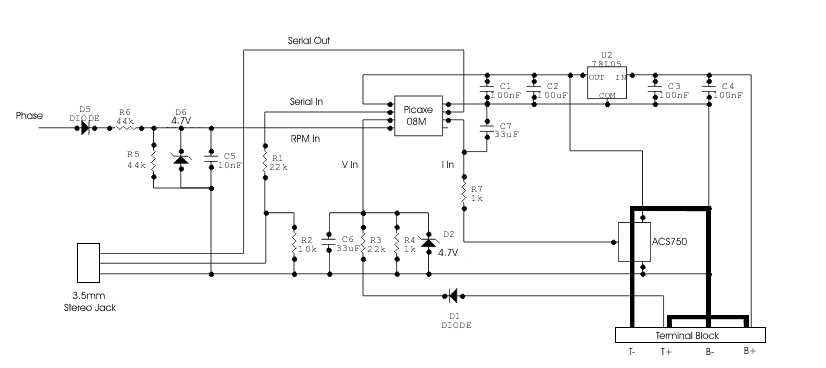
Voltage/Current and RPM will be measured using a picaxe micro as per this schematic:

The ACS750 is an Allegro hall effect current sensor and has a linear output up to +/-100A http://www.allegromicro.com/en/Products/Part_Numbers/0750/index.asp. The high current path from the turbine (T-, T+) to the battery (B-, B+) is shown in a heavy line. The terminal block is set up so the link between T+ and B+ can be removed to measure the unloaded RPM and voltage while still powering the circuit from the battery. With the link removed a purely resistive load can be connected between T+ and B- for testing. The voltage measurement is set up to measure up to 100V on the turbine side. The battery can be anything up to 30V limited by the max input voltage for the 7805. The RPM input is up to 100VAC from a single phase of the turbine. The diodes create a ~5V square wave +ve pulse used to measure RPM. A simple RC filter is used to cut out noise (diode switching from the rectifier) but limits the readable frequency to around 150Hz (1500rpm for your typical 12 pole alt)
The picaxe will transmit measurements via the serial cable to a laptop. The frequency of the transmission will be dependant on the RPM of the turbine due to the RPM measurement. The pulsin command that I will use to read the RPM, times out after in just under 1/3 of a second so there will be at least 3 transmissions per second. This will also limit the lower range of RPM measurement for my turbines to around 50RPM.
The laptop will be running MS Excel and I will use VBA to read the incoming serial data streams from both the GPS and the picaxe and place it directly into a worksheet. I have chosen this method purely because it involves the least effort on my part.
Initially I would like to determine the baseline performance of the cheap Chinese turbines I have imported and then use this information to determine the effects of the various modifications I have made. I also currently have a prototype MPPT controller based on a typical buck converter topology that works up to 100V input, 40A output on the bench. This has been designed with these small turbines in mind. Rather than build elaborate bench equipment to further test this unit, I’d much rather test it hooked up to a real wind turbine. Testing the buck converter functionality on the bench is not too bad but developing a MPPT algorithm that works in the real world should be easier this way.
More to follow...