Author Topic: Small Turbine Test Rig Part 1  (Read 4723 times)

0 Members and 1 Guest are viewing this topic.

jimovonz

  • Sr. Member
  • ****
  • Posts: 339
Small Turbine Test Rig Part 1
« on: May 21, 2007, 05:33:52 AM »
DanB's pics of the dump truck testing on Guemes Island has spurred me on to finishing off the electronics I needed to put together my own. I have been planning a test rig for my 2.2 and 2.5m turbines to put various modifications to the test. It will also provide valuable information for developing/testing my MPPT controller.


The plan is to mount a 2.7m pole for the turbine at the rear of a tandem trailer and tow it behind a vehicle using a computer to log speed, voltage, current and RPM. Measuring the air speed as seen by the turbine is problematic as the turbine itself affects the air stream so much when in operation. In addition to this, the vehicle itself will alter the air flow when in motion. To mitigate these variables I plan to place the turbine as far way from the vehicle as practical and do my best to measure true air speed as seen by the rotor. The turbine will be placed approx 4m behind the vehicle and approx 3m above the road. Before the turbine is mounted on the pole I will record data from an anemometer placed at the mounting point of the turbine as well as at the highest/lowest and widest points of the rotor. I will relate the data from the anemometer to GPS speed data for the vehicle to derive what is hopefully a reasonably accurate air speed as seen by the turbine w.r.t. vehicle ground speed. By picking a day where there is little to no wind and by taking an average of runs in opposite directions I can hopefully achieve good accuracy. Accurate true air speeds will be nice, but ultimately do not matter so much for good comparative data. Repeatable relative air speed measurements will be fine for determining the effects of my modifications.


The anemometer I will use is part of a 1-wire weather kit from AAG (http://www.aagelectronica.com/aag/en-us/p_1.html) similar to the one used at my weather station http://www.fieldlines.com/story/2007/3/14/14523/3589.


The vehicle speed (calibrated using the anemometer data to give air speed at the turbine) will be measured using a Garmin GPS 15 OEM sensor http://tinyurl.com/32l7qy (Sorry for the tinyURL but the real URL won't autoformat properly). I have a couple of these left over from an anti collision system I worked on a couple of years back. This unit is little bigger than a postage stamp and runs off 5V. It transmits NMEA position data via a RS232 connection once per second. The data includes ground speed accurate to approx 0.1 knots.


Voltage/Current and RPM will be measured using a picaxe micro as per this schematic:
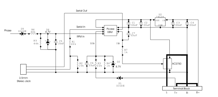


The ACS750 is an Allegro hall effect current sensor and has a linear output up to +/-100A http://www.allegromicro.com/en/Products/Part_Numbers/0750/index.asp. The high current path from the turbine (T-, T+) to the battery (B-, B+) is shown in a heavy line. The terminal block is set up so the link between T+ and B+ can be removed to measure the unloaded RPM and voltage while still powering the circuit from the battery. With the link removed a purely resistive load can be connected between T+ and B- for testing. The voltage measurement is set up to measure up to 100V on the turbine side. The battery can be anything up to 30V limited by the max input voltage for the 7805. The RPM input is up to 100VAC from a single phase of the turbine. The diodes create a ~5V square wave +ve pulse used to measure RPM. A simple RC filter is used to cut out noise (diode switching from the rectifier) but limits the readable frequency to around 150Hz (1500rpm for your typical 12 pole alt)


The picaxe will transmit measurements via the serial cable to a laptop. The frequency of the transmission will be dependant on the RPM of the turbine due to the RPM measurement. The pulsin command that I will use to read the RPM, times out after in just under 1/3 of a second so there will be at least 3 transmissions per second. This will also limit the lower range of RPM measurement for my turbines to around 50RPM.


The laptop will be running MS Excel and I will use VBA to read the incoming serial data streams from both the GPS and the picaxe and place it directly into a worksheet. I have chosen this method purely because it involves the least effort on my part.


Initially I would like to determine the baseline performance of the cheap Chinese turbines I have imported and then use this information to determine the effects of the various modifications I have made. I also currently have a prototype MPPT controller based on a typical buck converter topology that works up to 100V input, 40A output on the bench. This has been designed with these small turbines in mind. Rather than build elaborate bench equipment to further test this unit, I’d much rather test it hooked up to a real wind turbine. Testing the buck converter functionality on the bench is not too bad but developing a MPPT algorithm that works in the real world should be easier this way.


More to follow...

« Last Edit: May 21, 2007, 05:33:52 AM by (unknown) »

scottsAI

  • Hero Member
  • *****
  • Posts: 884
Re: Small Turbine Test Rig Part 1
« Reply #1 on: May 21, 2007, 08:09:52 PM »
Thanks jimovonz,


The link to GPS 15 was appreciated.

Not looked for quite a while, something I can use.


MPPT

Will this be a boost for low speeds, then revert to direct at higher wind speeds?

Or, MPPT over the entire power rang?


ACS750

If looking to take accurate data, may want to reconsider the hall sensor unless calibrated.

+-5% nonlinearity error, total output error is +-13%

Much of the 13% is offset error based on past current flows, not calibratable.


Nice project.

Have fun,

Scott.

« Last Edit: May 21, 2007, 08:09:52 PM by scottsAI »

jimovonz

  • Sr. Member
  • ****
  • Posts: 339
Re: Small Turbine Test Rig Part 1
« Reply #2 on: May 21, 2007, 08:49:28 PM »
No problem Scott. The GPS 15's are great little units, this one has been floating around one of my junk boxes for over two years and still works like a charm. I use a length of coax stripped back to give a full wavelength dipole antenna, using the roof of the vehicle as a ground plane. Very low tech but often have a lock on 8+ satellites. We ended up not using these units in favour of another with a 5Hz update frequency (a 10 tonne wheel loader can move quite far in 1 second!)


The MPPT is based on a buck converter and as it is can only step down the voltage, but will operate across the whole range once cut-in is achieved. I primarily designed this to use on the 12V version of the 200w turbines I have which is basically a turbine designed for 24V with a 12V regulator. I am hopeful that gains will also be made on the 24V version as well and will look at adding a simple boost fet using the turbine's inherant inductance in addition to the buck converter if it looks beneficial (separate buck and boost not buck/boost...) This turbine puts out around 80V at 600RPM with no load so I am hopeful of some reasonable gains.


The ACS750 could be better with regard to accuracy but as the schematic I presented is actually part of the controller I'm developing and I'm using it as is for this task, it will have to do. In a MPPT controller, relative current measurements will do a reasonable job of getting to the max power point. The error figures you quote are worst case over the entire operating range and are not so bad when used in a 'typical' environment. The expected variance due to past current flows is approx 0.3A @ 25degC after an excursion to 100A. Typical overall error over the full current range is 1.5% @ 25degC. I have already gone to some lengths to calibrate the readings from this device and am quite happy with the variance I see. If I get anywhere near 40A I'll be very happy!

« Last Edit: May 21, 2007, 08:49:28 PM by jimovonz »

domwild

  • Sr. Member
  • ****
  • Posts: 357
Re: Small Turbine Test Rig Part 1
« Reply #3 on: May 22, 2007, 12:56:44 AM »
Thanks for that. If I am not mistaken, did you lose a prop due to branches during previous tests?? If so, I wish you better luck this time!


I know you can design buck controllers yourself but what do you think of the latest buck controller chip from Linear Technology with inputs up to 100V? If you are intrigued, then I can dig up the number. Would this chip be a godsend to all those of us who cannot design a buck controller themselves?? The chip allows external synchronisation, so the Picaxe could provide the PWM to it?

« Last Edit: May 22, 2007, 12:56:44 AM by domwild »

jimovonz

  • Sr. Member
  • ****
  • Posts: 339
Re: Small Turbine Test Rig Part 1
« Reply #4 on: May 22, 2007, 01:39:09 PM »
Hey Dom, err... was that me was it...oh yeah... Yes, the last time I had a turbine on a trailer it was a 2m F&P: http://www.fieldlines.com/story/2006/2/27/0479/09688 This was one of the reasons I decided to use a computer to log the turbine data. I roped in a friend to drive the vehicle while I calibrated the outputs this time. Its way too easy to get carried away reading meters and forget to point the vehicle in the right direction! At least if it happens again its only a cheap chinese turbine and not a set of hand carved/glassed blades that I'd put a lot of time into...


Thanks for the heads up on the LTC3810. I have downloaded the datasheet and will go over it in detail soon. After a quick look it seems to have some nice features such as built in FET drivers, synchronous rectification and lots of protection. Ideally I think that 100V max might be a bit low (I've been designing to 200V max) but still workable. On first look it doesn't seem that you can externally control the duty cycle - the chip varies the duty to maintain a set voltage as per the Vfb pin and will synch its frequency as per the MODE/SYNCH pin and no other apparent way of directly controlling output current (which is what you are looking to do with a MPPT controller). There is quite possibly a way to do this using some of the other feedback mechanisms. I don't necessarily think that this chip will make it any easier for folk. Controlled as you are suggesting it basically becomes a FET driver for which the like of the IR2110 does a reasonable job.

« Last Edit: May 22, 2007, 01:39:09 PM by jimovonz »