Author Topic: Boost converter  (Read 8221 times)

0 Members and 1 Guest are viewing this topic.

willib

  • SuperHero Member
  • ******
  • Posts: 2414
  • Country: us
Boost converter
« on: June 06, 2007, 05:00:18 AM »
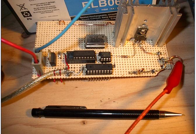
I moved my boost circuit off the breadboard and made it portable

It runs on 6V or 12V

the battery powers a 7805 for the PIC16F88 The clock and a 74LS161


the FET driver is powered directly by the battery , and feeds the FET with the PWM from the PIC.

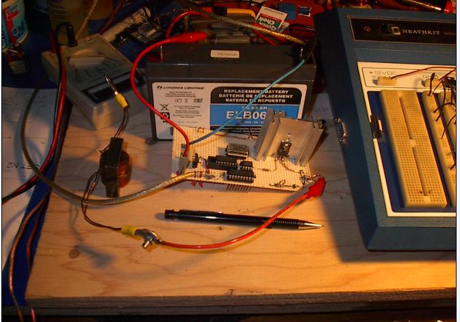
not shown are the 2 one farad caps in parallel that i use between the alt and the converter also not shown is the pot on the other end of that recycled USB cable , that i use to vary the pwm

the caps serve to sort of buffer the alt from the pwm , and this way the alt can get ahead of the pwm if the wind allows it to


during testing the boost doesnt mind at all if the alt and cap voltage is greater than the load battery voltage  


The boost converter can still double as a step down dc to dc converter or a hot wire foam cutter, just by bypassing the diode and the inductor

i used wire wrap sockets , but ended up soldering them anyway

i also put a 10 Ohm resistor between the fet driver and the gate because i thought it may protect the gate a little better than without it


as you can see i now have some more room on the breadboard


the goal of all this is to get some more power from the minigen II during low wind days , the other day when i took it out for a spin , it never stopped turning ,but it would only charge a 12V battery at or over 220 RPM


« Last Edit: June 06, 2007, 05:00:18 AM by (unknown) »
Carpe Ventum (Seize the Wind)

jimovonz

  • Sr. Member
  • ****
  • Posts: 339
Re: Boost converter
« Reply #1 on: June 06, 2007, 02:13:07 AM »
Looks good willib! Do you have any plans on how you will regulate the pwm to achieve charging in low winds? Keep us posted with your results.
« Last Edit: June 06, 2007, 02:13:07 AM by jimovonz »

willib

  • SuperHero Member
  • ******
  • Posts: 2414
  • Country: us
stall question
« Reply #2 on: June 06, 2007, 07:52:17 PM »
I took the boost converter out for a spin today

and i must say that it was a resounding sucess!


If the blades were turning it was charging

i would turn the pwm up or down depending on the wind, turning it up produced more current , at one point i was boosting an Amp and a half

there were gusts ,that i needed no boost and it still charged

those Foam Art blades as they have been called , really kick ass !


to your question i think if i was to go for the most current all the time , and the wind was really low to varible , there would be a point when the caps, between the alt and the boost converter, got so depleated , that the alt would run in constant low TSR , unless the wind picked up of course.

Because there were times that i let the caps charge up , by turning down the boost


could someone describe Stall to me ? durng stall are the blades still turning?


if stall means that the blades stop and the wind is still blowing then i have never seen stall

« Last Edit: June 06, 2007, 07:52:17 PM by willib »
Carpe Ventum (Seize the Wind)

harrie

  • Sr. Member
  • ****
  • Posts: 365
Re: stall question
« Reply #3 on: June 06, 2007, 08:16:33 PM »
Hi Willib, I wish I was on top of electronics enough to keep up with what your doing, but to answer your question on stall, ITs my thinking that stall is where your blades have reached a point that they will not increase in RPM any longer, but are still turning. My 18 foot, is always in stall at 48 RPM, it will not go any faster no matter what the wind does. hope that makes sence to you.
« Last Edit: June 06, 2007, 08:16:33 PM by harrie »

jimovonz

  • Sr. Member
  • ****
  • Posts: 339
Re: stall question
« Reply #4 on: June 06, 2007, 08:47:15 PM »
That must have been a satisfying outing for you! Getting something where you would otherwise get nothing has to be good. If you include yourself in the system, you could say that you have a MPPT controller! Though I can't see you taking on that position long term... Obviously there is no one pot postion (pulse width) that will suit all pre-cutin conditions. You can either boost a little using a fixed pulse width and keep out of stall, or use some 'smarts' to get the most possible from all conditions. I was doing some similar testing when I lost a turbine to some trees http://www.fieldlines.com/story/2006/2/27/0479/09688 though I was using a buck converter to reduce the voltage from an unmodified F&P smartdrive (still had a pot to 'twiddle' tho!).

Stall as we normally refer to it is a loss of lift due to increasing the AOA past some critical point and is caused by the cessation of laminar flow around the aerofoil. There are degrees of stall so its not a case of lift/no lift but rather a decreasing lift with increasing AOA. The F&P I just refered to when direct connected to a 12V battery stalled at around 10A @ 20km/h. The RPM/output remained fairly constant right up to the furling point. The voltage generated by the unmodified alt attached to the 12V battery was just too much load for the turbine. Attached to the buck converter I saw over 50A into the battery with a considerable increase in RPM past 20km/h.
« Last Edit: June 06, 2007, 08:47:15 PM by jimovonz »

willib

  • SuperHero Member
  • ******
  • Posts: 2414
  • Country: us
Re: stall question
« Reply #5 on: June 06, 2007, 08:49:17 PM »
Yes it does thank you harrie


as you said of your machine if its spinning , ITS Charging

your machine is in a different league than mine


does your machine ever stop spinning?

what current does your machine charge at on a mild night in the summer?

« Last Edit: June 06, 2007, 08:49:17 PM by willib »
Carpe Ventum (Seize the Wind)

harrie

  • Sr. Member
  • ****
  • Posts: 365
Re: stall question
« Reply #6 on: June 06, 2007, 08:57:03 PM »
yes, there are times it stops, I think because it is located on the shores of the Mississippi River, it is able to get a steady breeze most of the time. IT charges at a average of 4 Amps in 12 volt. I only use it to power our small boat house, that has a upstairs glassed in room for just siting and looking over the river. Of course sometimes I sneak down there and take a nap. Ha.
« Last Edit: June 06, 2007, 08:57:03 PM by harrie »

jimovonz

  • Sr. Member
  • ****
  • Posts: 339
Re: stall question
« Reply #7 on: June 06, 2007, 09:00:12 PM »
If your turbine operates too far from its design TSR, you will encounter stall.  If you try and boost too much power into you battery in low winds, the load presented to the turbine will cause it to slow (not enough power captured by the wind to meet the power draw). As the RPM reduces, the AOA increases and at some point you reach stall. This causes a reduction in lift which reduces RPM further but the reduction also means less voltage generated which reduces the load. The system will find an equilibrium point where the load matches the output of the generator, just on the stall point.
« Last Edit: June 06, 2007, 09:00:12 PM by jimovonz »

willib

  • SuperHero Member
  • ******
  • Posts: 2414
  • Country: us
Re: stall question
« Reply #8 on: June 06, 2007, 09:17:40 PM »
Yes it was extremely fun

a while back i was thinking of modifing the stator , with  one phase wound with a smaller gauge like  20 AWG , just to get something out of it in low wind , sort of a hybrid three phase axial flux alt, now i dont have to

Right now i have 4 coils per phase with 80 turns of 0.045"dia wire , 16 poles on each rotor

i'm gonna have to get a shot of the blades i'm using , they look a lot different than they used to
« Last Edit: June 06, 2007, 09:17:40 PM by willib »
Carpe Ventum (Seize the Wind)

Flux

  • Super Hero Member Plus
  • *******
  • Posts: 6275
Re: stall question
« Reply #9 on: June 07, 2007, 01:18:48 AM »
Others have covered this pretty well. Stall doesn't imply the blades stopping.


As Jimovonz has said there is no one pwm setting that will suit all winds. You need to feed back a speed or current signal to control the pwm to keep you on the peak of the power curve for your prop.In theory you can derive the peak power point by dithering the pwm and looking at the response. As you are a microprocessor wizard you may get it to work, but the analogue way does work and I have used it for years. In the boost region your blades need to increase speed directly with wind speed ( you have no choices beyond the boost phase).


I think you monster super capacitors will confuse any control scheme in normal winds. Even if you change pwm to suit the new wind speed the alternator is effectively bogged down into a battery ( capacitors) for a long period and by the time you have gained control the wind will have changed.


Now you have seen the benefits of the scheme you can concentrate on making a close approximation to mppt in the boost region.


Flux

« Last Edit: June 07, 2007, 01:18:48 AM by Flux »

willib

  • SuperHero Member
  • ******
  • Posts: 2414
  • Country: us
Blade shots
« Reply #10 on: June 07, 2007, 12:48:05 PM »
The blades themselves are 19.5" tall

but the distance from the center to tip is 24 7/8"

The changes i've made are , i ommitted the 21" taperless root section and i added some solid mahogany to the base

they are about exactly half their final size


Due to their construction ,they dont flex that much at all ,and i have extra tape on the leading side , where all the force is pushing them


I'm not shure how the tape will hold up if i added the rest of the sections , probably not too well , but for now it works great


a shot of the airfoil shape


The trailing edge got a little banged up in the trunk , but they are hanging in there


« Last Edit: June 07, 2007, 12:48:05 PM by willib »
Carpe Ventum (Seize the Wind)

alancorey

  • Full Member
  • ***
  • Posts: 129
Re: Boost converter
« Reply #11 on: June 07, 2007, 03:39:08 PM »
Glad to see you've gotten back to the PIC and this project.  I see you've changed to the PIC16F88, weren't you using a PIC12F683?  External oscillator too I see.


I finally got around to putting my programmer together this past weekend and it works.  I've been able to load the firmware with MPLAB, do the self-tests, and also played around a bit from the Unix side with Piklab which also sees and tests it OK.  My connectors took until earlier this week to show up so I've been reading the PIC12F683 datasheet and other stuff.


These may border on excessive inputs, but I was wondering about taking one of your fan/anemometers and sticking it on the back of a windmill, and feeding that into the PIC.  It would have a much faster response time than the RPMs detected from the alternator, so it could give advance warning of when the wind was slowing down or speeding up, which might be more helpful than trying to adjust the pulse duration after the change has had an effect on the blade and alternator.  I'm still trying to decide on the best way to get RPM data into the PIC, it seems like an F/V converter like the LM2917 fed into the analog inputs is more practical than trying to bother the PWM generation capabilties of the PIC by having it try to capture some cycles of alternator output directly.  I suppose a pair of FETs could be used to multiplex the 2 RPM signals through the same F/V and A/D channels.


Another input I've been thinking about is output voltage.  The approaches I've seen so far like jimovonz's algorithm at http://www.fieldlines.com/comments/2006/11/26/22831/362/11#11 are only aimed at getting the maximum current output, they don't deal with when the battery's charged.  Maybe it's best to cross that bridge when we come to it, but it seems like a good idea to plan ahead.  I see one of your drawings at http://www.otherpower.com/images/scimages/2965/new_boost_4.JPG has essentially boost, buck and dump load, but I'm not sure how you're planning to detect when to use which.


It seems strange to be using a PIC which thinks in microseconds to deal with a windmill that has a response time of 1/2 second or more at best.  What to do with all the extra cycles?  Do more A/D conversions and average them?  Look at first derivatives?  Probably can't do SETI in 256 bytes of ram.


  Alan

« Last Edit: June 07, 2007, 03:39:08 PM by alancorey »

jimovonz

  • Sr. Member
  • ****
  • Posts: 339
Re: Boost converter
« Reply #12 on: June 07, 2007, 04:41:04 PM »
Alan, I successfully measure RPM by converting the AC voltage on one phase to a 5V square wave then measureing the time between the rising edges on a single digital input pin (with a simple RC filter). This can be seen in this schematic: http://www.otherpower.com/images/scimages/2210/TurbMon.gif

Regulating the charge into the battery is relatively straight forward. I typically use N FETs to switch a dump load across the battery from the low side using pwm. There are a number of ways you could implement this on the pic with multi stage charging not much more difficult than your simple 'bang bang' single set voltage type. Having an initial set point somewhere around 14.4V will achieve a bulk and absorption phase and then dropping down to around 13.8V after a set time for your float. I check the voltage once every loop cycle and alter the pwm duty either up or down depending on the measured voltage relative to the target voltage. In the absorption phase I count cycles to determine when to initialte the float phase. Depending on what else your pic is doing this may give you a less than accurate absorption period. If this is a concern you could always look at using a RTC. I let the voltage go anywhere in the 13.8-14.4V range during this phase but restart the count if the voltage drops below 13.8V for more than a few minutes. I've tried pwm frequencies from 1kHz up to 100kHz (with suitable FET gate drive), all with success. I generally keep the frequency low to try and minimise the load on the FETs.
« Last Edit: June 07, 2007, 04:41:04 PM by jimovonz »

Ungrounded Lightning Rod

  • SuperHero Member
  • ******
  • Posts: 2865
Re: stall question
« Reply #13 on: June 08, 2007, 10:04:20 PM »
You should be able to get enough information by measuring the input voltage and output current of the booster to determine which way to adjust the pulse width.


Not sure what the function would be.  But you can measure the wind-speed.voltage.current three-tuple and find the max power point for each of several wind speeds, then turn that into a function of current vs. voltage that your microprocessor controller tries to track.


Raising the current will always lower the voltage and vice-versa.  So if you set up your controller to try to adjust the current toward the level appropriate for the observed voltage, and make the loop response slow enough for the mill rotation speed to react, it should track the measured-and-computed max-power curve closely.

« Last Edit: June 08, 2007, 10:04:20 PM by Ungrounded Lightning Rod »

jimovonz

  • Sr. Member
  • ****
  • Posts: 339
Re: stall question
« Reply #14 on: June 08, 2007, 10:58:38 PM »
ULR, while I'm sure this method would yeild good results, I don't know that its necessary to pre-define any particular MPP curve. I am getting good results 'chasing' the max power point purely based on current measurements. Change the pulse width, see if a gain or loss is made then either do the same or opposite depending on the result. This method is universally applicable, not specific to any particular setup, does not require any testing to measure MPP and is simple to implement on a microcontroller (no lookup table or complex computation).
« Last Edit: June 08, 2007, 10:58:38 PM by jimovonz »

jimovonz

  • Sr. Member
  • ****
  • Posts: 339
Re: Boost converter
« Reply #15 on: June 09, 2007, 12:58:20 AM »
willib, you mention using a '74LS161'. I presumed that this was the driver IC you refered to but a search on this number only turns up a 4 bit binary counter.
« Last Edit: June 09, 2007, 12:58:20 AM by jimovonz »

willib

  • SuperHero Member
  • ******
  • Posts: 2414
  • Country: us
Re: Boost converter
« Reply #16 on: June 09, 2007, 02:56:25 AM »
Yes , it divides the crystal modules 19Mhz signal , the output from the LS161 goes to the clock input on the pic


with the 74LS161 i can instantly change the clock input to the pic and hence the pwm frequency , by a factor of 2 , 4 , 8 or 16 , just by selecting one of the four counter output stages

i think i've found the best frequency for the inductor i'm using , but i may still tweak it some more


The driver IC is a TC4428A from microchip

« Last Edit: June 09, 2007, 02:56:25 AM by willib »
Carpe Ventum (Seize the Wind)

jimovonz

  • Sr. Member
  • ****
  • Posts: 339
Re: Boost converter
« Reply #17 on: June 09, 2007, 03:18:06 AM »
Wouldn't it have been easier to change the frequency in software? I have been setting up another pot to vary frequency to find the optimum for various inductors.
« Last Edit: June 09, 2007, 03:18:06 AM by jimovonz »

Ungrounded Lightning Rod

  • SuperHero Member
  • ******
  • Posts: 2865
Re: stall question
« Reply #18 on: June 09, 2007, 10:28:28 AM »
ULR, while I'm sure this method would yeild good results, I don't know that its necessary to pre-define any particular MPP curve. I am getting good results 'chasing' the max power point purely based on current measurements. Change the pulse width, see if a gain or loss is made then either do the same or opposite depending on the result. This method is universally applicable, not specific to any particular setup, does not require any testing to measure MPP and is simple to implement on a microcontroller (no lookup table or complex computation).


Sounds good to me.  (A time-domain approach, rather than the usual frequency-domain approach of deliberately dithering the load around a center on a slow cycle and slowly moving the center in the direction that improves the output.)


A peak-finder will be just about dead-on when the wind is calm, but can chase phantoms when it's turbulent.  Table-driven approaches will always go in the "right" direction, responding faster.  But any error in the table or a change in the mill itself will make the setting they're seeking be somewhat off the peak.  Peak-finders (such as yours) should do better long-term unless your site is really turbulent.


I think there's a hybrid that would produce better results than either for turbulent sites:  Using a V/I/current-pulse-width and table-driven function for the inner loop for fast response to wind changes, and slowly updating the table to keep it accurate.  But that's just theorizing.

« Last Edit: June 09, 2007, 10:28:28 AM by Ungrounded Lightning Rod »

jimovonz

  • Sr. Member
  • ****
  • Posts: 339
Re: stall question
« Reply #19 on: June 09, 2007, 12:17:34 PM »
ULR, I have experienced pretty much what you described with a purely current based algorithm. I am working on a number of refinements to improve the response time - basically to get to the peak faster. Factoring in the change in RPM makes a big difference but I am still looking to improve the response when the power/wind is rapidly increasing. I am trying hard to avoid any sort of lookup table to make it as generic as possible. I still haven't managed to do get the whole lot together on my trailer mounted test rig but I'm hoping this will give me the information I need to make improvements.
« Last Edit: June 09, 2007, 12:17:34 PM by jimovonz »

BigBreaker

  • Sr. Member
  • ****
  • Posts: 302
Re: stall question
« Reply #20 on: June 10, 2007, 01:43:41 PM »
I recommended a table approach to someone else for this reason and it definitely prompted discussion (not all in agreement).


Tables are great because they avoid "searching" behavior and because you can automatically start stalling the turbine as the wind gets too high.


I think people like the feedback approach because it makes the turbine seem intelligent.  I have played around with feedback in EE courses and it is really neat.  The problem is that it is tough to avoid oscillations with PID feedback and enforce boundary conditions.  Tables are not as "magic" but they always work and they don't need to approach the answer over time - they just skip right to it.

« Last Edit: June 10, 2007, 01:43:41 PM by BigBreaker »

jimovonz

  • Sr. Member
  • ****
  • Posts: 339
Re: stall question
« Reply #21 on: June 10, 2007, 03:05:26 PM »
I think that a table approach would still involve some degree of searching as altering the load changes the input parameters. It would still have to 'settle' onto the MPP for a given wind. You can exploit various properties of the wind turbine system to augment the feedback algorithm to avoid large oscillations around the MPP and improve response. Enforcing boundary conditions coundn't be more straight forward using a microcontroller. I have already incorporated an rpm limiter (by stalling the blades) in the algorithm without the use of a table. I have not been able to adequately test this feature due to the undersized alts on these chinese turbines being unable to hold back the blades. I am building a beefed up version of the buck converter to handle higher loads. I'll try it on my 3.6m dual rotor axial which should do better. Obviously this feature will still work in conjunction with a furling tail but should hopefully allow the turbine to maintain a high output past where it would otherwise have to furl. I also delay applying any control until the turbine reaches a minimum charging threshold.

I am confident that I can achieve a very reasonable response time using this type of algorithm. Significant effort would be required to map out a turbine MPP curve for a table lookup and the results would only apply to that specific system. Things like battery state of charge and attached loads which affect the loading on the turbine are automatically accounted for in my algorithm. If your lookup table specified the required current rather than pulse width for what ever inputs you choose, then you are still in a situation where you have to 'search' for the right pulse length to achieve the specified current.

As you say, not everyone is in agreement. I appreciate a view from a different perspective.

The proof of the pudding is in the eating!
« Last Edit: June 10, 2007, 03:05:26 PM by jimovonz »

willib

  • SuperHero Member
  • ******
  • Posts: 2414
  • Country: us
Re: stall question
« Reply #22 on: June 11, 2007, 01:55:04 AM »
Thanks for the reply Flux , the caps i was using between the alt and the boost was not the large bank of 350F caps , but was the two 1F caps in parallel ( auto audio caps ), they take a lot less time to charge up ..

i may change to just one 1F cap though , these are rated at 24V peak each IIRC

i'm not sure but the boost  seemed to work better with the caps , need to retest without the caps to be sure though , if the boost works as well without the caps i'll leave them out
« Last Edit: June 11, 2007, 01:55:04 AM by willib »
Carpe Ventum (Seize the Wind)

willib

  • SuperHero Member
  • ******
  • Posts: 2414
  • Country: us
Re: stall question
« Reply #23 on: June 11, 2007, 01:58:38 AM »
been working on trying to get a LCD display to cooperate with a PIC , not feeling very wizard like , at the moment

i've eliminated all possible wireing falts ,i think  so it must be the program

the only thing it does is change the contrast , no digits , nothing ...

a large chunk of the weekend down the crapper oh well..
« Last Edit: June 11, 2007, 01:58:38 AM by willib »
Carpe Ventum (Seize the Wind)

BigBreaker

  • Sr. Member
  • ****
  • Posts: 302
Re: stall question
« Reply #24 on: June 11, 2007, 12:58:20 PM »
It is true that if the input to the table is sourced from the turbine, than there is still searching.  I would use a anemometer as the input - not the turbine.


It is also true that the table needs programing and that takes some time.  Voltage is proportional to the wind speed, so there is a starting point.


I don't think the load should matter.  The batteries will take your current but it needs to be delivered at the right voltage.  MPPT is taking care of that.  Any load on the batteries will just compete for that current.

« Last Edit: June 11, 2007, 12:58:20 PM by BigBreaker »

jimovonz

  • Sr. Member
  • ****
  • Posts: 339
Re: stall question
« Reply #25 on: June 11, 2007, 02:01:08 PM »
I hope you don't think I'm being too critical of your ideas, I have given this topic much thought and my comments are in the spirit of good debate and help to further my understanding as much as anything else.


I would use a anemometer as the input

True instantaneous (relative!) wind speed from an anemometer would have its own problems. You would have to account for the delay in the response of the blades to wind changes. To get the best response time I believe there would still be a degree of 'searching'.


Voltage is proportional to the wind speed, so there is a starting point

I presume you are refering to unloaded voltage (rather than the voltage clamped by the battery). If you are switching at any reasonable frequency then sampling the voltage while the turbine is disconnected during an 'off' in the pwm cycle would be difficult. Stopping and starting the pwm in order to take voltage readings is problematic also. I think that rpm would probably be a better index to the lookup table.  


I don't think the load should matter"

If your table is set up to give you pulse length/duty based on whatever index, then I imagine that the load would have a reasonable effect. If your battery level is low and under reasonable load then the system voltage could be down around 11V. When lightly loaded and fully charged its up around 14V. That represents a significant difference in the amount of current that will flow for a given pulse width. You will have a significant variation in the loading for a given duty. To get around this loading issue you could use current as the output from your table so that for any windspeed (from your anemometer) or rpm you have a target current (into the battery.) However this approach would still leave you to 'search' for the appropriate duty to achieve the target current.

« Last Edit: June 11, 2007, 02:01:08 PM by jimovonz »

willib

  • SuperHero Member
  • ******
  • Posts: 2414
  • Country: us
its alive!
« Reply #26 on: June 11, 2007, 08:24:21 PM »
well its a start !!


I put the 877A on a vector wirewrap board , reloaded an earlier program , and this is what i got so far

« Last Edit: June 11, 2007, 08:24:21 PM by willib »
Carpe Ventum (Seize the Wind)

willib

  • SuperHero Member
  • ******
  • Posts: 2414
  • Country: us
at last !! the LCD works
« Reply #27 on: June 11, 2007, 11:45:03 PM »
the pot at the top left of the photo is hooked to the PIC channel 2 analog input

as you can see it reads 3.378 volts


this is the first time ,ever , that i was able to get a display of what the PIC was reading


i realize that this isnt really related to the boost circuit , but what the hey.

its all part of the same outcome

and this is a massive step forward for me

« Last Edit: June 11, 2007, 11:45:03 PM by willib »
Carpe Ventum (Seize the Wind)

jimovonz

  • Sr. Member
  • ****
  • Posts: 339
Re: at last !! the LCD works
« Reply #28 on: June 12, 2007, 12:22:51 AM »
That looks great willib! I have an 18 pin pic all setup to drive an lcd via a simple single pin serial interface. I simply program one up and add it to the project - it makes things very simple. A 16x2 line LCD + pic cost around $US25. I have also used cheap RF transmitter/recievers to transmit back to a PC for display. I am considering integrating these into the controller I'm developing.
« Last Edit: June 12, 2007, 12:22:51 AM by jimovonz »

willib

  • SuperHero Member
  • ******
  • Posts: 2414
  • Country: us
Re: at last !! the LCD works
« Reply #29 on: June 12, 2007, 10:55:10 AM »
it was easy to calibrate


just by altering the program
« Last Edit: June 12, 2007, 10:55:10 AM by willib »
Carpe Ventum (Seize the Wind)

BigBreaker

  • Sr. Member
  • ****
  • Posts: 302
Re: stall question
« Reply #30 on: June 12, 2007, 12:34:45 PM »
Yes - I see the issue you sight with the anemometer.  I would still avoid using the stator output directly.  Perhaps opto coupling, but I would prefer a small magnet on the rear rotor and a small, stationary pickup.  Isolation is important when working with ICs and those stator outputs could kick out something nasty.


Yes by voltage I meant unloaded IE when it is proportional to RPM.  So definitely using RPM is better.  The voltage would always be loaded when it matters.


A heavily loaded system will have a lower voltage, but wouldn't the turbine supply enough current to cure that?


The rectifier, battery and inverter are wired in parallel.  Heavy current from the battery will see some internal resistance - that's the source of the voltage sag.  Any meaningful current from the turbine will offset that current demand and bring the voltage up.  I can see a situtation where the battery bank and the turbine struggle to produce enough power.  There would be a small efficiency hit in that case, since the turbine would be optimized to deliver a slightly higher voltage.

« Last Edit: June 12, 2007, 12:34:45 PM by BigBreaker »

jimovonz

  • Sr. Member
  • ****
  • Posts: 339
Re: stall question
« Reply #31 on: June 12, 2007, 01:29:47 PM »
I certainly won't argue with isolation being a good idea on the input to IC's. However I have not had any trouble on the unisolated rpm input as described here I have had this circit (or something very similar on various turbines for quite some time. I would personally prefer not to have another set of leads down the tower but I see nothing wrong with a pickup like you describe. Adding an optoisolator to the digital output of my rpm circuit would achieve similar.


Loading on the battery does cause a voltage drop due to internal resistance, but I only added this to give an extreme example. The bigest cause of voltage fluctuation is the state of charge (presuming the battery is sized correctly for the load!)


I think that the best results would be obtained from a 'learning' algorithm. Using the method I have been advocating to 'find' the MPP and recording long term (relative) averages in a lookup table. That way you can get very close to the right loading for a given system state by looking up the value from the table, then fine tuning it using the search method. Any system changes would result in a slight performance hit until the new data filters through to the table. This would also have the advantage of not needing particularly accurate initial values when the system is first put into use.

« Last Edit: June 12, 2007, 01:29:47 PM by jimovonz »

BigBreaker

  • Sr. Member
  • ****
  • Posts: 302
Re: stall question
« Reply #32 on: June 13, 2007, 09:58:37 AM »
Funny that you mention using the results of the feedback control to program the table.  That's exactly how I would do it.  The resulting table could be edited to stall at the desired RPM, remove outlying values and eliminate any cycling that showed up.


I'll take a look at your RPM sensor.  My ideal turbine would have a yaw motor, rotor brake, powered furl or other mechanical method for additional protection.  If the stator burned up, the coil would still see the magnet on the back of the rotor and the PIC could direct some last ditch effort to stop the turbine.  I wanted the RPM sensor to survive just about anything.


If the only method of stopping the turbine is to short out the stator, then it doesn't really matter.  A burned out stator means the PIC can't do anything to stop it anyway.


Glad to hear that you are having such good success with wind MPPT.

« Last Edit: June 13, 2007, 09:58:37 AM by BigBreaker »