Author Topic: 07-07-07  (Read 1424 times)

0 Members and 1 Guest are viewing this topic.

Capt Slog

  • Sr. Member
  • ****
  • Posts: 378
07-07-07
« on: July 08, 2007, 09:40:07 PM »
Saturday was the day when it all finally came to gether and I got my firsy build up in the air.


I have no means of welding, so the whole thing has to be bolted together.  The chasis is a nice thick block of aluminum, its nealy an inch thick by about 4" wide. The main rotor axle goes through a threaded hole in this block.  The stator is supported by a round disk of some strange plywood that I found; it's hardwoood ply, sandwiched between 1mm aluminium.  Strong stuff and very light, the diskyou can see is painted silver to selathe edges so lookslike solid metal.


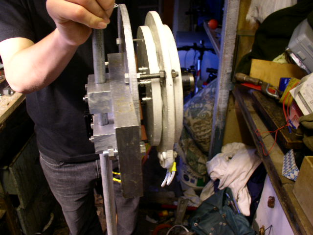
I made a three phase rectifier out of stud diodes, this is bolted to the back of the plate housed in a little box.  There is a heatsink on the box lid, but this is mainly for show as I doubt I willever see enough power to get it that warm!


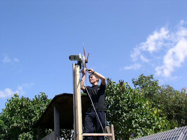
I've made a furling tail usin a standard door hinge, but mounting it at an angle.  The angle of the hinge on it's mount is around 20 degrees, and this plate can be mounted at afurther angle to the aluminum block.  I haven't done the calculations, but everything is adjustable, and I can tune it later. Those same green mounts are on the tail vane, so it can be slid along the tail bar.


Here you can see it fitted....


and furled.....


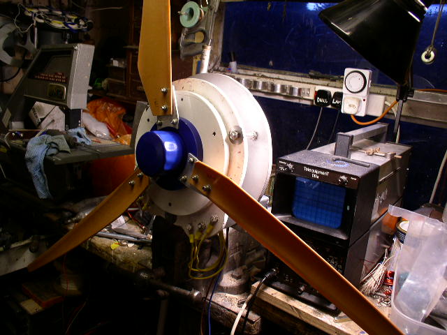
Here are the blades fitted to the rotors.  The blades are mounted to an aluminium ring boss (blue) and held to the rotor by six bolts coming all the way through.  See earler diaries for details.  The nuts are under that blue dome which if a cut-down GM cartidge oil filter.


This is my son Steve (Chip Slog) making some adjustments before we mount it on the tower


And here he is again making the connections.  The tower is a piece of scaffolding tube attatched to the tree house.  There is a shaft with bearing going down into the tube.  You can't see it here because it's top if flush with the woodwork, this turbine will be raised vertically by winching up the base of the tube.


When it's up it looks like this.


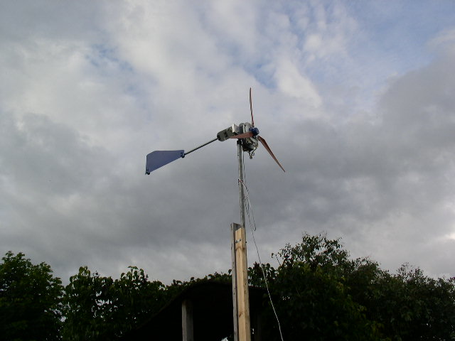
It will go higher than it isat the moment, and it will creep up there a bit at a time over summer so as not to frighten the locals!


So far, I'm not getting a lot of power, in fact almost none.  I have it hooked up to two very small 12 volt batteries which power some garden lights, and I see hardly any charge current.  I did have a car bulb (21W) on it at first just for braking, and when I connected this when it was spinning quickly, I managed to blow the filament.  But it won't light such a bulb in the wind I have, the blades are not upto the job.  They are about 3' 8" diameter and don't have enough twist at the root.  I'm planning to put 4.5 feet blades on, and mount them for a bit more twist.


Thanks for looking.

« Last Edit: July 08, 2007, 09:40:07 PM by (unknown) »

s4w2099

  • Full Member
  • ***
  • Posts: 234
Re: 07-07-07
« Reply #1 on: July 08, 2007, 05:16:54 PM »
Hey, Looks Nice, could you please repeat the specs of the alternator so that we can comment on the blades?

« Last Edit: July 08, 2007, 05:16:54 PM by s4w2099 »

oztules

  • Hero Member
  • *****
  • Posts: 1477
  • Country: aq
  • Village idiot
Re: 07-07-07
« Reply #2 on: July 08, 2007, 05:53:44 PM »
Well Capt,


Plenty of good skills there, cant help but feel this thing will get bigger as well as higher with time.


Interesting tail furl hinge..... in fact interesting all over.


Hope she holds together for you with the vibration over time.


good work


.........oztules

« Last Edit: July 08, 2007, 05:53:44 PM by oztules »
Flinders Island Australia

wooferhound

  • SuperHero Member
  • ******
  • Posts: 2288
  • Country: us
  • Huntsville Alabama U.S.A.
    • Woofer Hound Sound & Lighting Rentals
Re: 07-07-07
« Reply #3 on: July 08, 2007, 06:28:33 PM »
You know your gonna have good luck with it since you finished on the date 777 . . .
« Last Edit: July 08, 2007, 06:28:33 PM by wooferhound »

Flux

  • Super Hero Member Plus
  • *******
  • Posts: 6275
Re: 07-07-07
« Reply #4 on: July 09, 2007, 01:57:49 AM »
You will not get it to light a bulb directly in normal winds, as you say it will act as a brake. If it gets out of stall it will blow the bulb.


Your blades look to be very fast ( low solidity, high tsr). I seem to remember your alternator was fairly low speed cut in, but I have been rather busy lately and lost contact with some of this. If your blades start in a reasonably low wind then you may find a big improvement if you try a 24v battery and let the speed come up. I strongly suspect that those blades are being stalled and are never reaching operating speed.


For a low wind area you would be better with higher solidity blades intended to run at tsr 5 or near. Those blades you have would probably suit your alternator at 36v in a high wind area and push out lots of watts, but in a low wind region they will not be so good.


Flux

« Last Edit: July 09, 2007, 01:57:49 AM by Flux »

Capt Slog

  • Sr. Member
  • ****
  • Posts: 378
Re: 07-07-07
« Reply #5 on: July 09, 2007, 02:18:21 AM »
It's a 12 pole dual rotor using 24 of 1" x 3/8" N42 on 6mm steel discs. I think the gap is around 12-13mm.  The coils are 60 turns of swg 16 (I think thats around awg14) and at the moment it's wired in Star but can easily be changed.


I had these blade mounted on a modified minigen that I bought from Ed Lenz, and that's been flying for nearly a year.  I know it sounds ridiculous, but I'm sort of building this by stealth; I put something up and then modify it by degrees.


The next stage will be blade growth, going for something longer and with more curve.  Although I was disappointed, I can't really be surprised that the present ones don't work.

« Last Edit: July 09, 2007, 02:18:21 AM by Capt Slog »

Capt Slog

  • Sr. Member
  • ****
  • Posts: 378
Re: 07-07-07
« Reply #6 on: July 09, 2007, 02:25:24 AM »
I think in testing that the alternator gave 15v unloaded (after the diodes, and this was around 260-280 rpm; I've lost the figures I wrote down at the time but when you've only built one they stick in your memory.


I'd never considered going to a higher voltage, but I think I understand your point.  Yesterday I took the scope down the garden to check the DC was being rectified ok, and was slightly shocked (not literally) to see that I was getting 20-25volts in some gusts.

« Last Edit: July 09, 2007, 02:25:24 AM by Capt Slog »

RP

  • Hero Member
  • *****
  • Posts: 722
  • A dog with novelty teeth. What could go wrong?
Re: 07-07-07
« Reply #7 on: July 09, 2007, 09:21:15 PM »
Just for fun, you could try wiring your large bulb in series with an automotive relay (on the normally open contacts) and wire the relay coil across the genny output.  That way the bulb (load) won't be connected until you're up to 10 volts or so.


This may allow you to get out of stall and up to some reasonable speed before it gets loaded.  You could increase the "cut-in speed" by adding soem additional resistance in line with the relay coil.  


This made a big difference for a small Savonius I built a few years ago.

« Last Edit: July 09, 2007, 09:21:15 PM by RP »