Author Topic: Dump load controller on the ac side  (Read 6232 times)

0 Members and 1 Guest are viewing this topic.

alibro

  • Full Member
  • ***
  • Posts: 102
Dump load controller on the ac side
« on: December 18, 2007, 11:56:18 PM »
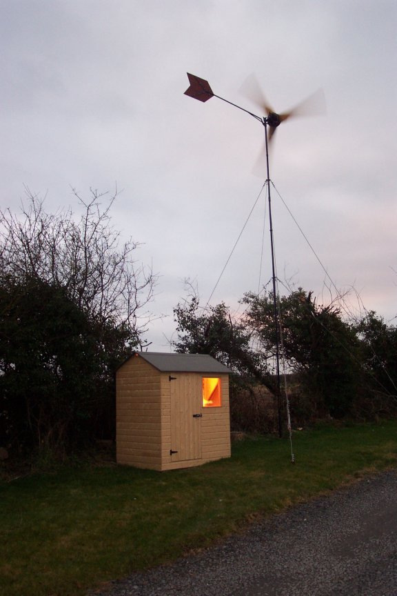
I have just got my Ghurd dump load controller working (in experimental mode) and thought I would share a little. My system is coming along painfully slowly but it is moving in the right direction. As the wind turbine is around 50m from the house I felt it was too far to bring low voltage. I also was too scared of the Boss to even suggest putting the battery bank in the house so I built a little shed at the bottom of the tower. In this pic I have a 500W halogen light powered from my 1400W UPS.


I have around 190Ah @24V of a battery bank, I know this is too small for my system but It is a start, I hope to upgrade it soon. The pic below shows some of the batteries I am using, They all came from old computer UPS's. You can also see the rectifiers screwed to a heatsink
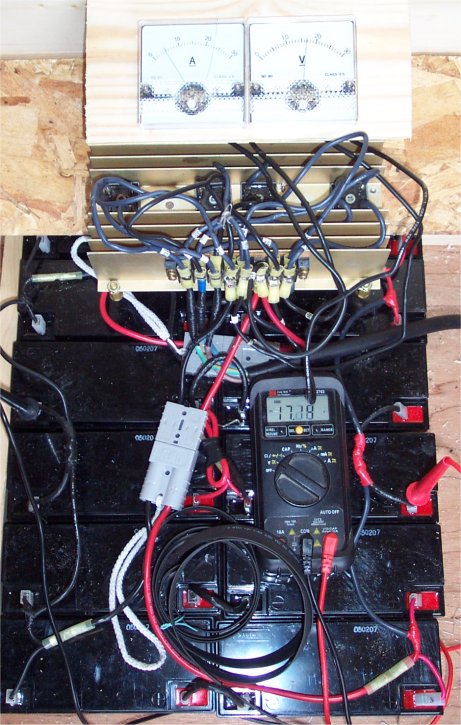


The wind was pretty light that day, the ammeter is on the left showing 5A and the voltmeter is showing 17.2V. When I found the batteries they were very low (around 6V) but seem to have come up quite well. The most power I have seen is >30A at >30V, I don't know the exact current as the meter was off the scale but I think I was seeing near 1KW. As this is a DanB Volvo brake disk 10 footer I guess I am doing well, maybe too well so I will be careful with it and first opportunity I will lighten the tail to let it furl earlier.

As the batteries charged I repeatedly saw voltages of 30V or more so I decided to get Ghurds little dump load controller going and the pic below shows how I connected it up.
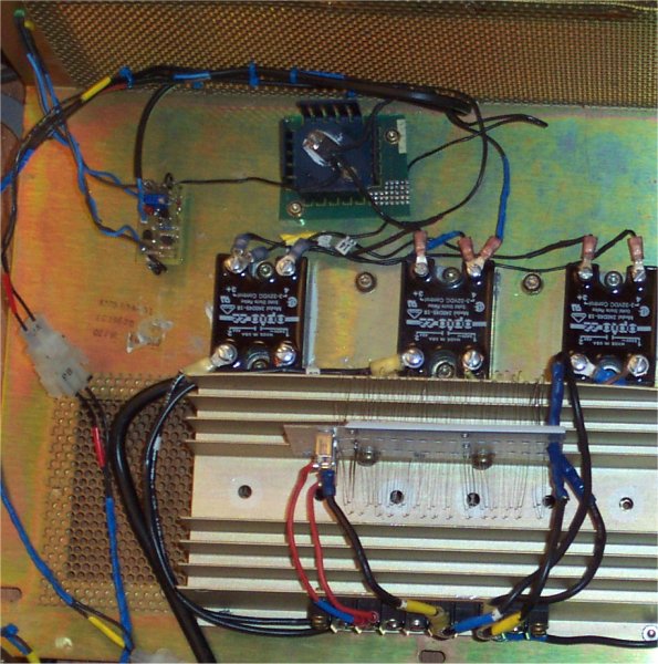


Glen connects his dump load onto the batteries but it was originally designed to handle 300W-600W and as I was seeing over 900W I decided to try something a little different. I also had a bunch of 45A ac solid state relays I got from some old computer mainframe kit which I was bursting to use. The pic above shows Glen's controller top left, the power FET top middle, then the three solid state relays and you can just see a portion of electric heater wire. When the controller triggers the FET switches 28.8V onto the solid state relays which then connects three lengths of heater wire across the three phases from the alternator. I didn't want to put too severe a load on the turbine so decided 300W was about right, I worked out what the resistance should be as follows.

When I saw approx 30Vdc I measured the ac voltage across 1 phase at approx 25V

I figured that if I dumped around 300W (100W per phase) I would need approx 4Ω across each phase. More by luck than skill I decided to cut the wire at 6Ω thinking I might change my mind. It was only when I had the wire connected and found it metered at 4Ω I realised by connecting them across each phase each resister wire was in parallel with the other two (in series) so each phase saw 4Ω almost exactly.

The pic below shows how it is all connected at the moment
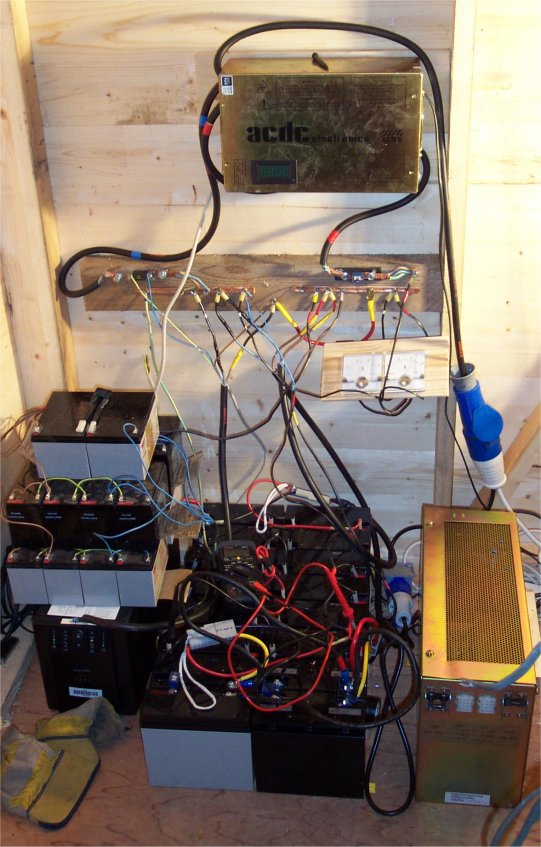


The box with acdc also came from old computer equipment so I thought it would be fun to put the rectifiers in it. I cut a hole and fitted a LED voltmeter/ammeter but I am not happy with it as the voltmeter seems to jump around a lot for no reason. I got some 10mm copper pipe, hammered it flat and folded it over to use as busbars. All the connections are held with woodscrews, screwed through it into the wood behind.

The 32A commando connector comes direct from the turbine so there is no concern about water getting in. So far I haven't had to untwist it. I also have another socket coming from the same cable which I can plug the brake into (a plug with three leads shorted). The box on the right has the dump load and you can just see the two led's at the far end of it. The gray cable in the foreground was just hanging up and got in the pic.

We had nice wind yesterday so I connected everything and let it go. The batteries came up to float voltage after a few hours and as I watched I could see the controller triggering every half second or so. I could feel heat from the resistance wire and the ammeter jumped up and down by at least 5-10 amps. I haven't done the maths yet but I guess it was dumping up to 250W.

As I said before this was an experiment and I can now see a couple of reasons for not putting the dump load across the ac side.


  1. As the ammeter is jumping up and down it is hard to see what the turbine is putting out.
  2. Ghurd says it is hard on the turbine. In my case the turbine seemed to continue spinning more or less at the same speed the whole time with only a slight change in the sound but Glen has much more experience than me so I will not argue with him
  3. As the dump load is not directly connected to the batteries I think it did not pull the voltage down as well as it would otherwise. This meant that even though the wind was not severe I saw the voltage rising above 29V.


Most of the work I did on connecting the controller is not wasted as I can use the same part of the heater wired slightly differently to put 6Ω or less (I will probably connect it for around 4Ω). I will need to connect a few more power fet's but it shouldn't be too hard. I will then build a second dump load controller and set it to dump at a slightly higher voltage.

Seeing it work was a lot of fun and feeling the heat generated by the product of ones own labours gave me quite a kick too.

A big thank you to Ghurd for help and advice with his little circuit
« Last Edit: December 18, 2007, 11:56:18 PM by (unknown) »

ghurd

  • Super Hero Member Plus
  • *******
  • Posts: 8059
Re: Dump load controller on the ac side
« Reply #1 on: December 18, 2007, 06:48:05 PM »
Wholly Crap!


Don't blame ANY of this on me because it is a success.


That is 110% your doing.


For #1. It is jumping up and down as the controller works.  The change is the difference between what the windmill is making compared to what goes into the battery and what goes into the dump load resistors.


For #2.  The turbine will act like someone jumped up to grab a blade when the resistance is `right' (a lot lower).  It will act like someone threw a tree into the blades.


For #3.  When the wind gets high, the low amp (high ohm) resistors will let it over-speed / over-power.  The better sized (lower ohm) resistors will straighten things out.  

(one way or another)  LOL.


The #2 & #3 are related.


For #4.  It is not safe, but it is nice to see about as many wires on a battery bank as mine.

(wear safety glasses. Only attempt outdoors. Make all moose wear safty glasses.)


Great write up, and I know there wasn't a #4.

G-

« Last Edit: December 18, 2007, 06:48:05 PM by ghurd »
www.ghurd.info<<<-----Information on my Controller

richhagen

  • Hero Member
  • *****
  • Posts: 1599
  • Country: us
Re: Dump load controller on the ac side
« Reply #2 on: December 18, 2007, 10:58:14 PM »
Nice looking little power shed.  Interesting application of Ghurds controller.  With the dumping on the AC side, you are not using the batteries to smooth out the voltage and loading on the Alternator.  Intuitively this seems less than ideal, but I can't argue with success.  If the dump load were larger/lower resistance, I would suspect that you would send the blades into stall when it connected and you would get a funny sound from them when the load connected in lower winds and there wasn't enough energy available to keep the blades spun up at a speed they want to run at.  With the loading on the DC side, the voltage/load that the turbine sees won't change that suddenly or severely.  Wow, that is a bunch of batteries!  With that many used UPS batteries connected together, I would probably try to check them fairly regularly - as my experience has been that one bad one will drag all of the batteries in parallel with it down rather quickly in times of no charging.  Rich
« Last Edit: December 18, 2007, 10:58:14 PM by richhagen »
A Joule saved is a Joule made!

Flux

  • Super Hero Member Plus
  • *******
  • Posts: 6275
Re: Dump load controller on the ac side
« Reply #3 on: December 19, 2007, 01:41:23 AM »
Dumping on the ac side does have one advantage in that a faulty controller doesn't drain the batteries flat.


I have done it in more elegant ways and it certainly is practical. I have certain reservations about doing it this way but even then it will probably be fine. It is rather cruel to the alternator and the blades but for smaller machines it may not be as bad as I would have originally expected. If the switching rate stays fairly high then it may be no worse than a single phase alternator with its inherent vibration and torque pulsation.


AirX gets away with something that has similar mechanical effects and I believe SWWP are trying it on bigger machines.


Anything strong enough to survive in a gale of wind probably is capable of taking this sort of loading in its stride, but if you ever witness a direct short on a 3 phase 1kW pma driven by a motor on a bench test you may share my initial fears. In this case it is not a direct short and nothing like as bad.


Just keep an eye on stator mounting bolts etc for a while or use plenty of loctite.


Flux

« Last Edit: December 19, 2007, 01:41:23 AM by Flux »

tecker

  • SuperHero Member
  • ******
  • Posts: 2183
Re: Dump load controller on the ac side
« Reply #4 on: December 19, 2007, 08:41:45 AM »
Series resistance is by far the best plan on the ac side nichrome reacts to the current through the  batts in an interesting way providing  balances to the low impedance of a charged battery  .Need only to jump around it when the voltage drops on the dc side . Of coarse you would  switch to a parallel connection for over voltage especilly with  alot of slas but really adding some current pigs (like a couple of 100 ah 6 volts) will make every thing work as they will balance the over charge instaed of a dump situation. .

« Last Edit: December 19, 2007, 08:41:45 AM by tecker »

Bruce S

  • Global Moderator
  • Super Hero Member Plus
  • *****
  • Posts: 5422
  • Country: us
  • USA
Re: Dump load controller on the ac side
« Reply #5 on: December 19, 2007, 11:01:25 AM »
alibro;

   Very nice setup.

The light coming from the shed is strangely comforting:-)

We keep seeing the success rates of G-'s dump controller and there'll be no living with him. What with him striving to become a dozen-aire and all.


Just think of all the batteries not in the dump, but living happily in your shed.:-)

Many thanks for the post.

Very nice indeed. I would ask though how much of the power you're gathering now are you using to offset the mains? or still experimenting?


Cheers

Bruce S

« Last Edit: December 19, 2007, 11:01:25 AM by Bruce S »
A kind word often goes unsaid BUT never goes unheard

alibro

  • Full Member
  • ***
  • Posts: 102
Re: Dump load controller on the ac side
« Reply #6 on: December 19, 2007, 02:18:25 PM »


  1. , It was great fun watching it switching but it's a bit hard to see at a glance what power I am getting.
  2. When we discussed using your dump load for this system you said it would be better to dump in two stages so I always intended this to be the first stage. I didn't want to stop the turbine completely as I figured it would be too hard on it. If I reconnect it to the dc side what resistance do you think I should use? I was thinking maybe 2Ω-3Ω would draw 250W to 400W. Alternatavly I could put the 2nd dump load controller onto the dc side at a lower voltage setting so that this one only cuts in when the wind is blowing hard.
  3. I know it looks like a rats nest of wires but with so many small sla's it is hard to keep it all tidy. I am hoping to get bigger batteries soon and sort it out properly.


Cheers

Alibro
« Last Edit: December 19, 2007, 02:18:25 PM by alibro »

disaray1

  • Full Member
  • ***
  • Posts: 196
Re: Dump load controller on the ac side
« Reply #7 on: December 20, 2007, 05:57:05 AM »
 Just an observation... an uncanny resembelence in system "A"..


 http://www.otherpower.com/images/scimages/2050/batmess.jpg


 and system "B"...


 http://www.otherpower.com/images/scimages/6667/Shunt_Load_xx.jpg


 Makes me wonder. :)


 David


« Last Edit: December 20, 2007, 05:57:05 AM by disaray1 »

ghurd

  • Super Hero Member Plus
  • *******
  • Posts: 8059
Re: Dump load controller on the ac side
« Reply #8 on: December 20, 2007, 08:41:11 AM »
It switches pretty fast, making it hard to read the amps.  

Plus, changing the AC side changes the windmill speed, which changes the output to 'analog'(?), constantly rising or falling, if you know what I mean.


The mill is making 1KW, so the DC side dump load needs to be over 1KW.

No idea how much it will make after lightening the tail.  It's still a lot of power.


Just a thought.  When the AC side has a dump load...

The mill will slow down, and it will have an impact on the furling?

Meaning furling would be related to the battery voltage.

That is my understanding of it.  It could be very flawed.  There could be other implications too.  Not sure if it is good or bad.

It's past anything I should be giving advice about.  :-/


Disaray's A to B comparision is a bit uncanny.

G-

« Last Edit: December 20, 2007, 08:41:11 AM by ghurd »
www.ghurd.info<<<-----Information on my Controller

ghurd

  • Super Hero Member Plus
  • *******
  • Posts: 8059
Re: Dump load controller on the ac side
« Reply #9 on: December 20, 2007, 08:54:50 AM »
If Flux says it is good to keep the switching rate high, might consider changing C1 to 1uF or 4.7uF.  It shouldn't make too much difference on the switching speed, but it wouldn't hurt.

G-
« Last Edit: December 20, 2007, 08:54:50 AM by ghurd »
www.ghurd.info<<<-----Information on my Controller

alibro

  • Full Member
  • ***
  • Posts: 102
Re: Dump load controller on the ac side
« Reply #10 on: December 20, 2007, 12:39:03 PM »
Somebody's been taking photos in my shed!!!!!


I'm to busy doing stuff to be tidying stuff!


Alibro

« Last Edit: December 20, 2007, 12:39:03 PM by alibro »

alibro

  • Full Member
  • ***
  • Posts: 102
Re: Dump load controller on the ac side
« Reply #11 on: December 20, 2007, 01:07:49 PM »
As this was only ever a fun experiment I will redesign it to dump on the dc side in two stages with a 2nd controller but here is a thought. The single controller is quite happily switching three 45A ac relays. There is no reason why I couldn't use it to switch a 40A dc relay which should be able to cope with 500W at 28V easily and with the 2nd dump load controller we're sorted!

Have I missed something, I feel like Dougal from Father Ted, 5 seconds after he comes up with a brilliant idea he just stands there being confused.


Alibro

« Last Edit: December 20, 2007, 01:07:49 PM by alibro »

alibro

  • Full Member
  • ***
  • Posts: 102
Re: Dump load controller on the ac side
« Reply #12 on: December 20, 2007, 01:14:47 PM »
Just a little subnote. This message is the first to be 100% powered by my wind turbine. I only tonight brought the mains lead from the shed into the house and just because I was busting to try it out I fitted a loose socket on the wire and brought the power up to my computer with an extension lead.


This feels GOOOOD!!!!!


Cheers All

Alibro

« Last Edit: December 20, 2007, 01:14:47 PM by alibro »

DamonHD

  • Super Hero Member Plus
  • *******
  • Posts: 4130
  • Country: gb
    • Earth Notes
Re: Dump load controller on the ac side
« Reply #13 on: December 20, 2007, 01:33:37 PM »
Yes, very kewl!


Rgds


Damon

« Last Edit: December 20, 2007, 01:33:37 PM by DamonHD »
Podcast: https://www.earth.org.uk/SECTION_podcast.html

@DamonHD@mastodon.social

wooferhound

  • SuperHero Member
  • ******
  • Posts: 2288
  • Country: us
  • Huntsville Alabama U.S.A.
    • Woofer Hound Sound & Lighting Rentals
Re: Dump load controller on the ac side
« Reply #14 on: December 21, 2007, 02:52:28 AM »
I keep looking at my Solar 12v CFL shining and I say

Wow, thats the Sun coming out again for the second time
« Last Edit: December 21, 2007, 02:52:28 AM by wooferhound »

alibro

  • Full Member
  • ***
  • Posts: 102
Re: Dump load controller on the ac side
« Reply #15 on: January 04, 2008, 10:25:59 AM »
Another wee update

I had to bring the turbine down a couple of days ago because I failed to follow good advice from this board and forgot to put locktite on the nuts holding the stator. As these nuts grip the resin directly they cannot be tightened as much as the others so they came loose (Big surprise!---NOT). While it was down I wanted to do something to help it furl earlier, I hadn't got any aluminum sheeting yet so instead I moved the wooden tail forward about 8 inches. I think it may have been longer than necessary and it still seems to be following the wind fine so I was pleased to see it furling at around 25-30 amps and 29V. It is a little hard to be sure but the change seems to have worked.

I have just received a 40A DC solid state relay and will try it out as a dump load switch. It may not work as the internal resistance might be too high A note in the eBay listing states "Although technology improvements are continually improving the contact resistance of SSRs, it is still not uncommon to find them in production today with resistances of 100 Ohms or more." I will post my findings soon. If anybody is interested here is the link to the eBay sight where I bought it complete with heatsink for £8 including shipping.


http://stores.ebay.co.uk/Sure-Electronics


Cheers All

Happy New Year

Alibro

« Last Edit: January 04, 2008, 10:25:59 AM by alibro »

alibro

  • Full Member
  • ***
  • Posts: 102
Re: Dump load controller on the ac side
« Reply #16 on: February 12, 2008, 02:13:29 PM »
This is a repost just so it is in my diary


Hi Guys

Last time I posted about my dump load controller, I had connected it to three ac solid state relays on the ac side of my turbine. I did it this way because I had the relays and I thought it might be fun to try something a little different. There are several reasons not to do it this way and if you are interested you can see the discussion in my diary. I still have this setup but will change it to operate on the DC side, it is really only dumping around 150W as it is.

Now I'm at it again!

I may have got this all wrong and Ghurd, please forgive me if I have, but I think the controller can handle several power fets and each can handle up to 6 amps but they need a separate load for each fet. The dump load I have came from a cheap room heater and is a bit awkward to break up into several separate loads. My solution was to buy a 40A DC solid state controller from ebay (for just over £8) and use a single fet to drive it. I then connected the whole dump load to it, along with a 24V fan.


The resistance of the load is 2Ω but I was uncertain of the SSR so I briefly forced the controller to stay activated while I took some readings.


Voltage dropped across the load (2Ω) is 26V

Voltage dropped across SSR is 2V


If my maths is correct that means the current through both is 13A

Therefore the load is taking 338W and the SSR 26W for a total of 364W.

The heater element got kind of hot but did not glow red and the voltage seemed to be controlled even with pretty strong winds showing up to 20A (with most of my batteries disconnected). I had intended to dump a bit more than 364W but accidentally connected a couple of extra loops of heater wire. I am not too worried though as I have another old heater and I will make the next one dump a bit more at a slightly higher voltage.


Before I buy another SSR for my second dumpload can anybody give any advice regarding the use of a DC Solid state relay for fast switching? I only tested it briefly and it seemed to be fine but I am a bit worried it might not last long. Here is a link to the auction


It is item number 350023778454 if you want to search ebay.com


Cheers all

Alibro

« Last Edit: February 12, 2008, 02:13:29 PM by alibro »