Author Topic: I broke it.  (Read 1047 times)

0 Members and 1 Guest are viewing this topic.

bigkahoonaa

  • Jr. Member
  • **
  • Posts: 57
I broke it.
« on: April 21, 2008, 03:35:32 AM »
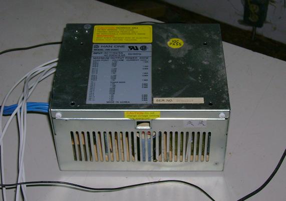
I built and tested a version of the circuit in this post.  I recycled many components from an old PC power supply:


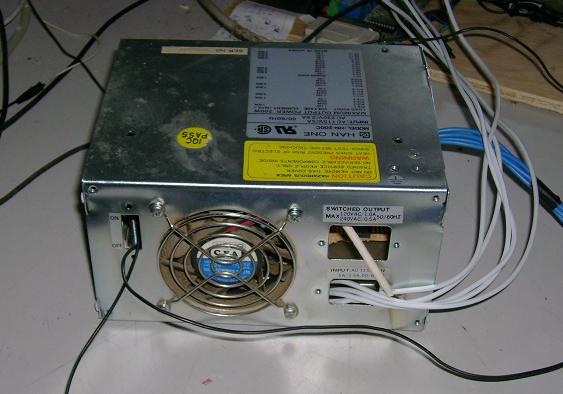
Bonus thing is that it has its own warning labels:


And cooling fan for when things get too hot:
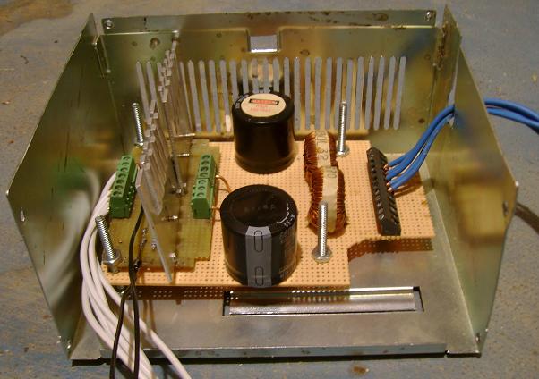


Inside:


I've been testing it in winds around 2 to 6 m/s and it works.  Genny performance can be changed by changing duty cycle.  The bad thing is that it has a narrow range, from about 1% duty to 4% duty.  Below 1% duty and it's an open circuit.  At 4% duty and higher, it's like being connected directly to batteries.


I set up the micro so it can run in auto or manual mode.  The micro will automatically adjust duty in auto mode, but the algorithm is probably not optimized.  I was using manual mode to see performance at a set duty and changing wind conditions.  It got away on me.  RPMs shot to over 300 in a wind gust, with dc voltage over 100.  Way too much for the poor old IRF540.  Now the genny putters along at 30 RPM regardless of wind.  Oh well, time to break out the soldering iron again.

« Last Edit: April 21, 2008, 03:35:32 AM by (unknown) »

Flux

  • Super Hero Member Plus
  • *******
  • Posts: 6275
Re: I broke it.
« Reply #1 on: April 22, 2008, 02:00:03 AM »
Yes making it survive in real life is more difficult than on a simulator. I think you have a problem with the narrow range of pulse width. I don't see any inductors in your practical device, those tiny toroidal things are going to saturate and you will be reduced to almost a charge controller type pwm.


Don't know why you need a fan, the hottest thing in my unit for a 6ft mill is the rectifier, there is virtually no heat from the rest.


You will have to choose mosfets to handle the open circuit voltage in a high wind or else design a voltage clipper ( however careful you are, it will see an open circuit machine one day).


I would expect you to need about 30% variation in pulse width to cover the range if it is working properly.


Keep at it you will get there and the reward is considerable in the end.


Flux

« Last Edit: April 22, 2008, 02:00:03 AM by Flux »

bigkahoonaa

  • Jr. Member
  • **
  • Posts: 57
Re: I broke it.
« Reply #2 on: April 22, 2008, 09:56:07 AM »
Hi Flux


The fan came with the PC power supply and I'd have a big hole if I took it out.  The picture is just my warped sense of humour.  I wasn't sure about using does toroid.   I did search this board and found lots of info but I don't understand saturation very well.  All seems like black magic to me.  I'm not an analogue guy.  I feel more comfortable with digital, but digital needs analogue interfaces.


"Yes making it survive in real life is more difficult than on a simulator."  I couldn't agree with you more.  Things can go terribly wrong terribly fast.  It took about 2 seconds for it to jump from 200 to over 300 RPM.  I was trying to keep it at about 200 RPM.  An 8 foot mill going at 300 RPM is a bit scary.


I was surprised by the narrow range of pulse width, but I'm not certain what needs changing to increase this range.  I'm replacing the fets with 400V versions.  That should be enough, with a very good safety margin.


Thanks for your help.  You are an asset to this board.


Big

« Last Edit: April 22, 2008, 09:56:07 AM by bigkahoonaa »

commanda

  • Hero Member
  • *****
  • Posts: 731
Re: I broke it.
« Reply #3 on: April 22, 2008, 10:04:23 AM »
I think you'll find those toroids are the output filters from your pc psu. I have used them for small converters, good for about 10 or 20 watts.


Amanda

« Last Edit: April 22, 2008, 10:04:23 AM by commanda »