Author Topic: My next windmill - Part 1  (Read 6340 times)

0 Members and 1 Guest are viewing this topic.

TheCasualTraveler

  • Sr. Member
  • ****
  • Posts: 404
My next windmill - Part 1
« on: April 26, 2009, 06:17:03 PM »
     On the way to building my second windmill I ran into builders block. I realized my current setup with small sealed ball bearings wasn't enough. I did not want to go the trailer hub route either but I did want to use the same bearings as in the 4" trailer hub. I have spent quite a bit of time over the last year staring at different bits and pieces, trying to put them together into some sort of workable unit.


     So, my goal; a setup that requires no plasma cutter, no welder, no lathe and really just needs a few hand tools to build the main assembly, less the alternator. A 6 foot and under mill that either uses stall limiting or no furling. A setup that anyone in the US could copy with a shopping list and few visits to the Ace hardware and building supply stores. Oh, and it also uses the same tapered roller bearings as the 4" trailer hub. I believe the original idea came from something in Ghurd's files so credit where it's due.
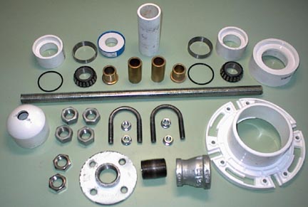

     Here's the bits.


Next,


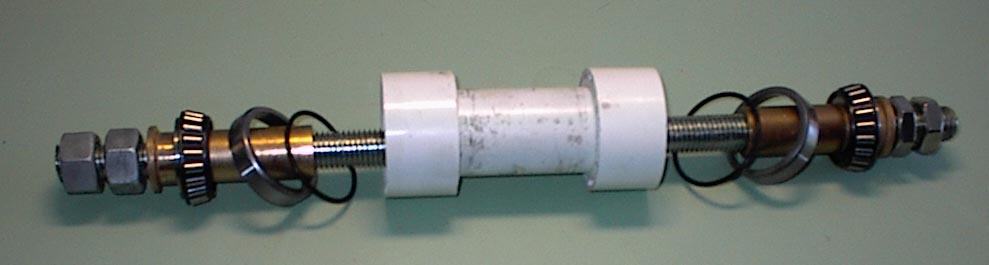
Partially assembled,


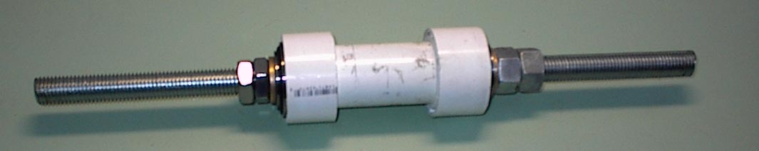
adding the down pipe,


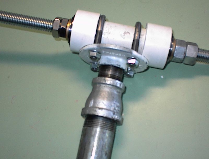
Stator support and front bearing cover,


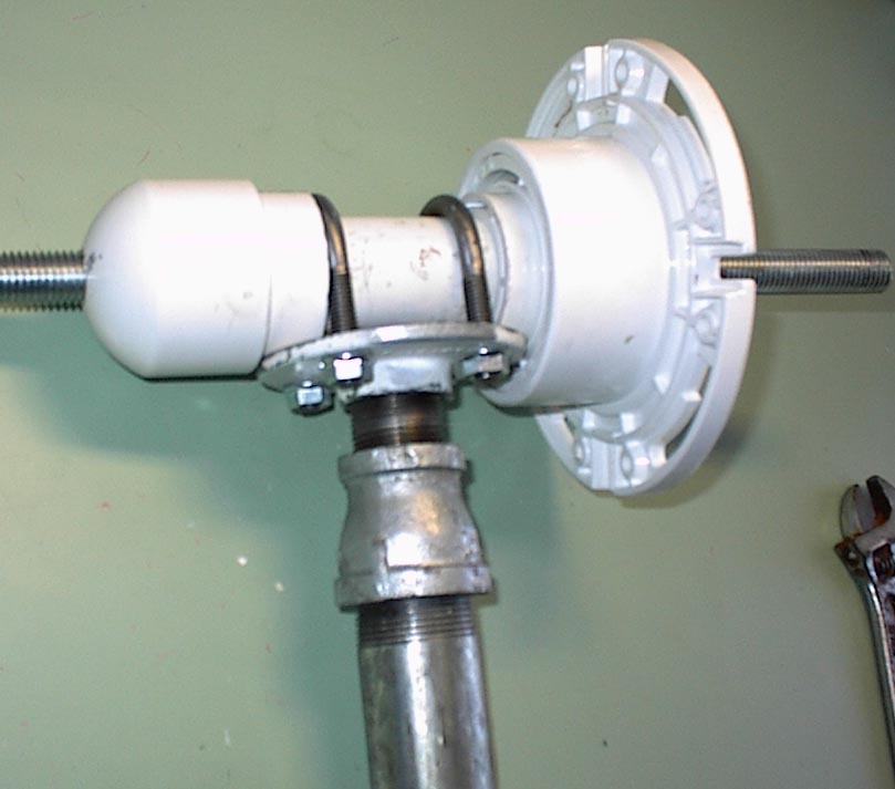
     The blade set will go on one end and the alt on the other. Everything is mounted on a 3/4 rod of all thread. The threads are set so that when the prop is turning the shaft the threads will push water out in a corkscrew fashion to protect the front bearing. Also the front bearing cap will have a weep hole at the bottom to drain any water that makes it's way in. The rear bearing will be protected by the stator support (not in the picture. Everything will get a few coats of Rustoleum to protect from rust and the PVC from UV.


     Why did I do it all this way? I wanted very much to build a small mill but knew I never would if I needed welder, lathe and the like. Also, I think there are many others that get discouraged from building a small mill and either quit or go the route of looking for treadmill motors and the like because it's easier, even if the results are disappointing.


     So there it is. Assembly time from the first picture to the last is about 10 minutes. Shopping time for the bits, a little longer. My six foot wood carved blades are already made and ready to be mounted and the alternator is on my bench just waiting for the stator to be poured before the final assembly. I really hope this is useful to folks with limited tools and I have no doubt it can be improved upon.


     Oh and thanks, I couldn't have done it without YOUR help.  


(please let my pictures be the size that right clicking says they are)

« Last Edit: April 26, 2009, 06:17:03 PM by (unknown) »

Stonebrain

  • Sr. Member
  • ****
  • Posts: 342
Re: My next windmill - Part 1
« Reply #1 on: April 26, 2009, 02:24:45 PM »
Great engineering and great pics!

Know that,spending hours in the shop playing with plumbing parts,and ending up becoming suspect...


Thanks a lot


cheers,

stonebrain

« Last Edit: April 26, 2009, 02:24:45 PM by Stonebrain »

willib

  • SuperHero Member
  • ******
  • Posts: 2414
  • Country: us
Re: My next windmill - Part 1
« Reply #2 on: April 26, 2009, 02:35:47 PM »
It looks nice.

Sort of like Jerry's setup , i like the fact that yours can have the alt on one end and the blades on the other..


Have you seen or have considered using two pillow block bearings ?

Keep up the good work !

Bill

« Last Edit: April 26, 2009, 02:35:47 PM by willib »
Carpe Ventum (Seize the Wind)

TheCasualTraveler

  • Sr. Member
  • ****
  • Posts: 404
Re: My next windmill - Part 1
« Reply #3 on: April 26, 2009, 02:49:29 PM »
     Yes Bill, your right. That's where I got the idea, Jerry's files not Ghurd. Sorry for the mix up guys. Yes I tried smaller bearings like Jerry did but it's really hard on them. I also considered pillow blocks but I felt going with the tapered roller bearings left little room for improvement. Thanks for looking.
« Last Edit: April 26, 2009, 02:49:29 PM by TheCasualTraveler »

kurt

  • Hero Member
  • *****
  • Posts: 925
  • Country: us
    • website
Re: My next windmill - Part 1
« Reply #4 on: April 26, 2009, 03:06:09 PM »
there have been allot of reported failures with threaded pipe joints the pipe tends to shear off right were the pipe screws into the fitting after a wile numerous people have reported that failure TomW for one that i can remember right off the top of my head
« Last Edit: April 26, 2009, 03:06:09 PM by kurt »

TheCasualTraveler

  • Sr. Member
  • ****
  • Posts: 404
Re: My next windmill - Part 1
« Reply #5 on: April 26, 2009, 03:14:58 PM »
     Yes Kurt, I read that more than once. I wonder what size mills they were. I thought for a 6' mill the strain might not be so great. My first mill had a threaded connection at the top, but it was PVC! Actually lasted 6 months and took a lot of wind before it gave out.
« Last Edit: April 26, 2009, 03:14:58 PM by TheCasualTraveler »

TheCasualTraveler

  • Sr. Member
  • ****
  • Posts: 404
Re: My next windmill - Part 1
« Reply #6 on: April 26, 2009, 03:46:18 PM »
     OK, I searched and found Tom's post on the threaded pipe failure. Also I examined that threaded nipple and the thickness of the metal at the grooves is ridiculously thin. Thanks for the heads up.

     At the bottom of Tom's post someone suggests using a schedule 80 fitting there instead of schedule 40. Tomorrow I will see if I can find a schedule 80 fitting and see if it appears suitable.

     Thanks again for the warning.
« Last Edit: April 26, 2009, 03:46:18 PM by TheCasualTraveler »

PHinker

  • Jr. Member
  • **
  • Posts: 94
Re: My next windmill - Part 1
« Reply #7 on: April 26, 2009, 04:35:13 PM »
I did something similar to this a while back.  With some simple parts from Ace Hardware.  1/2 inch shaft, couple bearings, couple shaft locks, and a piece of emt.  Everything fits together surprisingly well.  Add your yaw bearing bits and the C clamps and you're off.


« Last Edit: April 26, 2009, 04:35:13 PM by PHinker »

hiker

  • Hero Member
  • *****
  • Posts: 1661
  • BIG DOG
Re: My next windmill - Part 1
« Reply #8 on: April 26, 2009, 10:45:39 PM »
heres another simple and sturdy setup...

couple of block bearings at each end--3- 2by4s laminated togeather-forms the main mount.

furling tail.. built it for my old rv..its held up now for a number of years..

i choped the blades down somewhat-than what shows in the pict..didnt need all the power it was putting out..stator is held on by shelf hangers with holes drilled throu for bolts...blades were made from ceader fence boards-with airfoil on back side-tapered

front..hub made from a couple of plywood disks[laminated togeather]with angled cutouts

for the blades-3 bolts per blade...


« Last Edit: April 26, 2009, 10:45:39 PM by hiker »
WILD in ALASKA

bob g

  • Hero Member
  • *****
  • Posts: 1107
  • 8.8kwatt idi diesel thermal conversion unit
    • microcogen.info
Re: My next windmill - Part 1
« Reply #9 on: April 27, 2009, 03:38:02 AM »
you might also consider carving your blades so that the threaded shaft

turns counter to the threads, this will aid in "screwing" dust/dirt out of the

front housing.


probably would work better with fine thread shaft (allthread)


bob g

« Last Edit: April 27, 2009, 03:38:02 AM by bob g »
research and development of a S195 changfa based trigenerator, modified
large frame automotive alternators for high output/high efficiency project X alternator for 24, 48 and higher voltages, and related cogen components.
www.microcogen.info and a SOMRAD member

Ungrounded Lightning Rod

  • SuperHero Member
  • ******
  • Posts: 2866
Re: My next windmill - Part 1
« Reply #10 on: April 27, 2009, 01:57:23 PM »
Be sure to paint any exposed PVC tubing to block ultraviolet.
« Last Edit: April 27, 2009, 01:57:23 PM by Ungrounded Lightning Rod »

TheCasualTraveler

  • Sr. Member
  • ****
  • Posts: 404
Re: My next windmill - UPDATE
« Reply #11 on: May 02, 2009, 02:02:48 PM »
     OK,having been warned about the chance of a failure from using a schedule 40 galvanized pipe nipple, I procured a schedule 80 close nipple which is heavier than your standard galvanized pipe. For a small mill I think this should be ok now. Also, the fact that this setup has blades on one end and the alt on the other end balances the weight better and may cause less stress. This does, however, really screw up my plan that someone can get all the bits shopping locally in one afternoon. I had to special order the schedual 80 fitting. Oh well, I'll work on that part of the design.


     So I packed the bearings and assembled it for the last time. It was pretty stiff with the new grease so I added a few drops of oil and loosened things up. Then I mounted my six foot wood carved blades on it and took it out to my test pole for a little free wheeling fun.


     The wind was light today and I thought it would do no harm for some freewheeling to get those new bearings loosened up.


      The six foot blades LOVE the new bearings. My old mill running unloaded was just casually spinning but the new mill took to making those whirring noises right off the bat.

     So, now the builders block I had is gone and I can get back to finishing the alt. Coils are already wound and laying on the wife's dryer like they have been for the last 3 months. They are 65 turns of 18 AWG.


      The rotors are 10" by 1/4 steel with Ed's wedge magnets on one disc, the other disc will be blank. Here's a shot of my test gig. Notice the stroboscope stuck to the rotor. That's how I check RPM's. I use a DC motor with a PWM speed controller to set the speed. There's a program I use that will create a stoboscope for any RPM you input. At 150 RPM's I was getting about 1.65 volts ac. I estimate cut in anywhere from 170 to 200 for 12 volt.


     I used bronze spacers to set my airgap. I would never get it right trying to adjust nuts. The air gap is around 11/16". I anticipate a stator around 7/16 "


     Hope you enjoyed the pictures and I hope they were all proper sized.

« Last Edit: May 02, 2009, 02:02:48 PM by TheCasualTraveler »

lucas

  • Newbie
  • *
  • Posts: 5
Re: My next windmill - Part 1
« Reply #12 on: May 02, 2009, 04:01:53 PM »
Cool design. when it gets up and running I'd like to see some hard numbers.

looks like something I could even build:)


                   Lucas

« Last Edit: May 02, 2009, 04:01:53 PM by lucas »

ghurd

  • Super Hero Member Plus
  • *******
  • Posts: 8059
Re: My next windmill - Part 1
« Reply #13 on: May 02, 2009, 08:12:01 PM »
Neat use of getting stuff to fit together.


How does the yaw work?  Galvanized over the white pipe?  

Everything looks the same size.


Lock Tight on the muffler clamp nuts?

G-

« Last Edit: May 02, 2009, 08:12:01 PM by ghurd »
www.ghurd.info<<<-----Information on my Controller

TheCasualTraveler

  • Sr. Member
  • ****
  • Posts: 404
Re: My next windmill - Part 1
« Reply #14 on: May 02, 2009, 08:51:24 PM »
        Neat use of getting stuff to fit together.


Thanks.


        How does the yaw work?  Galvanized over the white pipe?  

        Everything looks the same size.


Thats my test pole. The bottom of the pipe on the mill rests on top of a pvc sleeve clamped to a pipe that runs up thru the other pipe. Just pipe on pipe but with the weight bearing on the pvc collar below. Actually, I just looked at that picture. Thats how my old mill was. This one is bearing at the top of the pipe. If you look there is about a 4" gap between the pvc sleeve and the down pipe of the mill. The basic idea was this - rather than have metal pipe grinding on metal pipe I put a pvc fitting at the bottom of the down pipe and a pvc sleeve on the pole, then greased up the pvc joint. No big deal and no real difference from pipe on pipe.


       Lock Tight on the muffler clamp nuts?


Nope, just tightened. Their serrated. On my old mill, flying for a year they were still snug.


Thanks for looking.

« Last Edit: May 02, 2009, 08:51:24 PM by TheCasualTraveler »

zeusmorg

  • Sr. Member
  • ****
  • Posts: 363
Re: My next windmill - Part 1
« Reply #15 on: May 09, 2009, 11:24:47 AM »
 This looks like a very interesting way to get a smaller mill up in the air, and anyone could do it. It may be nice to provide a parts list, sizes and such to make it easier for others to copy your accomplishment.


 Well done!

« Last Edit: May 09, 2009, 11:24:47 AM by zeusmorg »

TheCasualTraveler

  • Sr. Member
  • ****
  • Posts: 404
Re: My next windmill - Part 1
« Reply #16 on: May 09, 2009, 12:33:27 PM »
Thanks zeusmorg,


     I poured my stator this morning. In a few days I will have results and in the meantime I am putting together a pictorial and parts list. So far it has worked well mechanically and is very solid.


For fun I put the blades on backwards and let it run without a tail as a downwind turbine. I'm not sure if that will work once the alt is on but I'm going to try it.

« Last Edit: May 09, 2009, 12:33:27 PM by TheCasualTraveler »

TheCasualTraveler

  • Sr. Member
  • ****
  • Posts: 404
Re: My next windmill - Part 2
« Reply #17 on: May 22, 2009, 09:18:39 AM »
     Well, my new rectifiers arrived (thanks Ghurd) so I finished things up and it's flying. Wind was good today except that it's ESE which is dead foul for my test pole mounted beside my house. Even so it put out up to 100 watts when the wind managed to twist around the house.

     I'm very happy with it and it is running very smooth and quiet. With what I learned here I was able to guess cut in pretty accurately. Here's a shot,


     The whole project can be seen here,

http://www.thecasualtraveler.com/wind.htm


     Thanks everyone for your help and patience.


The next step will be to harvest the 12 magnets identical to this machines magnets that are stuck to my old machine, thus turning this one into a true dual rotor. I brought all the wires out of the stator and can play with Jerry rig later.

 It's been a long strange trip to this point, I'm glad it's done. Well, almost...

« Last Edit: May 22, 2009, 09:18:39 AM by TheCasualTraveler »