With my
Electric Hubcap[TM] motor [www.TurquoiseEnergy.com] not having enough torque to hit the streets, I got the idea of an in-line torque converter, and, using magnets and axial flux, how about an axial flux magnetic torque converter?
I have the thought that if it's efficient, it could possibly be good for a windplant as well: by regulating the load, you could maintain a constant generator speed and hence voltage (or frequency if that's important), while the prop went faster and slower with the wind speed. The power from a stronger wind could come out as higher current at the same voltage.
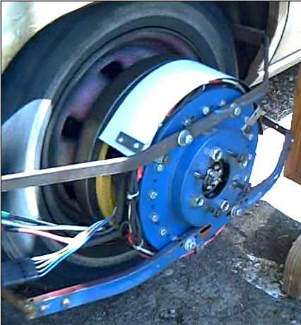
I put together a magnet rotor - the back side of the motor rotor (yellow) - and an aluminum plate rotor mounted in a "frying pan", fixed to the wheel:

Someone pointed out that this would transfer torque at reduced speed, but there would be no more torque than was originally applied by the motor, the slip energy simply being dissipated as heat. It's a "torque resistor" instead of a "torque transformer".
Then I added radial slits across the area swept by the magnets to directionize the induced current flow:
(Hmm, I can't seem to place the picture. It uploaded itself to directory "." that I can't access at "Select File".)
However, that's not the whole answer either. Whereas the solid plate rotor would have had a linear slip torque curve, with the slits it might have more of a NEMA type D rotor slip curve, still the same and highest at the low end, but staying higher until getting near synchronous speed. That's replacing the simple "resistor" with a non-linear "resistor".
I'm convinced this is doable and practical, and it's just a matter of figuring out the right configuration. A fluid torque converter has three elements, the impeller, the turbine and the stator. The stator takes the "equal and opposite reaction" back-pressure of the liquid as back torque on a piece that won't turn backwards.
Some third element is probably the missing piece of the puzzle, that needs to redirect the electrons or the "magnetic back pressure" of the magnetic torque converter, to make it into the "torque transformer" instead of "torque resistor".
Maybe the slotted rotor needs to turn within the aluminum pan, which is fixed rather than rotating, and somehow the magnet rotor, induced (slotted aluminum) rotor, and pan "case" need to be somehow electromagnetically linked, to produce a working unit.
Hmm... What would happen if the slots were extended around, so the pan had radial slots on the bottom face as well as on the fixed aluminum plate - a double sided, slotted, non-rotating cylinder "case" - and the bottom drove another magnet rotor on the wheel? The fixed case would then be the fulcrum against which the higher speed, lower torque of the motor rotor and the lower speed, higher torque of the wheel rotor would act. Could the currents through the aluminum, instead of simply dragging on the motor rotor, transfer "all" the flux across while allowing different shaft speeds and torques?
--Craig