Author Topic: Magnetic Torque Converter  (Read 5868 times)

0 Members and 1 Guest are viewing this topic.

CraigCarmichael

  • Newbie
  • *
  • Posts: 34
Magnetic Torque Converter
« on: June 03, 2009, 08:02:01 PM »
With my Electric Hubcap[TM] motor [www.TurquoiseEnergy.com] not having enough torque to hit the streets, I got the idea of an in-line torque converter, and, using magnets and axial flux, how about an axial flux magnetic torque converter?


I have the thought that if it's efficient, it could possibly be good for a windplant as well: by regulating the load, you could maintain a constant generator speed and hence voltage (or frequency if that's important), while the prop went faster and slower with the wind speed. The power from a stronger wind could come out as higher current at the same voltage.


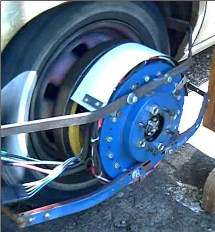
I put together a magnet rotor - the back side of the motor rotor (yellow) - and an aluminum plate rotor mounted in a "frying pan", fixed to the wheel:


Someone pointed out that this would transfer torque at reduced speed, but there would be no more torque than was originally applied by the motor, the slip energy simply being dissipated as heat. It's a "torque resistor" instead of a "torque transformer".


Then I added radial slits across the area swept by the magnets to directionize the induced current flow:


(Hmm, I can't seem to place the picture. It uploaded itself to directory "." that I can't access at "Select File".)


However, that's not the whole answer either. Whereas the solid plate rotor would have had a linear slip torque curve, with the slits it might have more of a NEMA type D rotor slip curve, still the same and highest at the low end, but staying higher until getting near synchronous speed. That's replacing the simple "resistor" with a non-linear "resistor".


I'm convinced this is doable and practical, and it's just a matter of figuring out the right configuration. A fluid torque converter has three elements, the impeller, the turbine and the stator. The stator takes the "equal and opposite reaction" back-pressure of the liquid as back torque on a piece that won't turn backwards.


Some third element is probably the missing piece of the puzzle, that needs to redirect the electrons or the "magnetic back pressure" of the magnetic torque converter, to make it into the "torque transformer" instead of "torque resistor".


Maybe the slotted rotor needs to turn within the aluminum pan, which is fixed rather than rotating, and somehow the magnet rotor, induced (slotted aluminum) rotor, and pan "case" need to be somehow electromagnetically linked, to produce a working unit.


Hmm... What would happen if the slots were extended around, so the pan had radial slots on the bottom face as well as on the fixed aluminum plate - a double sided, slotted, non-rotating cylinder "case" - and the bottom drove another magnet rotor on the wheel? The fixed case would then be the fulcrum against which the higher speed, lower torque of the motor rotor and the lower speed, higher torque of the wheel rotor would act. Could the currents through the aluminum, instead of simply dragging on the motor rotor, transfer "all" the flux across while allowing different shaft speeds and torques?


--Craig

« Last Edit: June 03, 2009, 08:02:01 PM by (unknown) »

Madscientist267

  • Hero Member
  • *****
  • Posts: 1181
  • Country: us
  • Uh oh. Now what have I done?
Re: Magnetic Torque Converter
« Reply #1 on: June 04, 2009, 09:57:35 AM »
Sounds like more or less you're talking about a modified eddy brake, only using it as a clutch with a load on the stator instead of a brake with a fixed stator... ?

 
« Last Edit: June 04, 2009, 09:57:35 AM by Madscientist267 »
The size of the project matters not.
How much magic smoke it contains does !

CraigCarmichael

  • Newbie
  • *
  • Posts: 34
Re: Magnetic Torque Converter
« Reply #2 on: August 10, 2009, 12:57:45 PM »
I haven't tried yet to put together the complete torque converter. I thought I'd cast around for more thoughts and ideas others may perhaps have, maybe starting with one to get imaginations rolling...


1. What if the torque was, eg, magnified by 10 for 1/10th of the time and zero for the remainder. Would that start the car moving? Obviously if it was zero for 10 seconds and 10 x for 1 second that would get it moving, then it needs less torque, sooner, to keep it moving. But what about very short periods? With friction overcome, the car moving just a bit, further high-torque pulses would continue to speed it up?


2. If that could work, then what about mounting magnets on a second rotor, on arms with springs holding them away from the spinning rotor? As a magnet that's attracting spins by one on an arm, as it nears opposition the magnetic attraction overcomes the spring and the magnet jumps into close proximity to the driving rotor (small gap).

   Then it's yanked along by the driving rotor until the attracting magnet has passed by. Then the arm springs back.

   The effect is the second rotor is pulled intermittently by a magnetic "yanking", magnetic pulses, without being slowed again by attraction in the wrong direction.

   With 10 magnets on the driving rotor, there could be 9 on spring arms on the second one and each turn of the first rotor would produce many short, strong pulls.


3. There are other mechanical ways to produce the one-way force. for example, the 9 magnets could be mounted so they could shift forward and backwards on the rotor by, eg, an inch. When an attracting magnet passed, it would again pull the second rotor, but it would leave that arm forward. When the next attracting magnet came by, when it got close enough it would suddenly pull the arm backwards until they were opposite each other, but exerting no force on the 2nd rotor. As it came forward to the end of the arm's travel, it would again pull the rotor forward until the magnet was past.

   A repelling magnet should work, too, but attracting and repelling ones might get in each others' way. The amount of travel of the arms, etc, would have to be carefully considered.


4. There's probably also ways to do it by twisting or flipping the magnets as they go by.


5. I can't help but think with the slotted stator or whatever that there must be ways to do this electromagnetically without invoking mechanical moving parts.


>Madscientist267


>Sounds like more or less you're talking about a modified eddy brake, only using it as a clutch with a load on the stator instead of a brake with a fixed stator... ?


   Sorry I never got back to you. I didn't quite understand what you were saying and I got onto other things - new motor controller, batteries and all.

   Basically, my idea is that the eddy currents are directionized via the radial slots, and the magnetic field they generate essentially transfers the field from the rotating supermagnets through to the other side of the stator.

   There, the field is picked up by a second rotor, which starts to turn. The magnetic thrust pushing the second rotor pushes against the stator instead of against the first rotor, so it's not loading against the first one directly. Presumably if it's going slower than the first one, the torque can then actually be higher. As the second rotor speeds up, it creates electromagnetic fields that counter the induced field, transfer back through the stator, and reduce the load on the first rotor inversely proportional to the difference in speed between rotors.

   If I've just repeated what I said before without shedding more light, it's probably because what the electromagnetic fields will actually be doing is still not entirely clear in my mind.


   I expanded on the idea also in Turquoise Energy News (#17 I think).

   http://www.TurquoiseEnergy.com/TENewslettersIndex.html


Cheers,

Craig

« Last Edit: August 10, 2009, 12:57:45 PM by CraigCarmichael »