Author Topic: charge controller for micro hydro  (Read 11856 times)

0 Members and 1 Guest are viewing this topic.

lofty

  • Newbie
  • *
  • Posts: 3
charge controller for micro hydro
« on: October 03, 2006, 09:53:54 PM »
Hello,


I'm volunteering at a place out in the country who are living off the grid. They already have a couple of windmills, which have been installed professionally. They are also working on a micro hydro system. This has been designed and partly built by a professional engineer during his spare time, but he has been unable to do any more work on it for some time (at least a year) due to other commitments. The turbine and alternator are finished, but none of the rest of the electrics, including the charge

controller for the batteries (it's going to be a DC system with an inverter).


They have just got hold of a battery backup system of the kind which is used to supply emergency power to alarm systems, emergency lighting etc. (I think it used to run the emergency lighting for a nursing home). This is designed to charge some 12V batteries from the 240V mains, and there is also a separate inverter which supplies mains power from the batteries.


I was talking to one of the people there, and he was talking about using the battery backup system as a charge controller for the water turbine. I was advising him to be cautious, for the following reasons:


  • you need to have some way of shunting power to a dump load when the batteries are fully charged and no current is being drawn, otherwise the turbine may overspin and damage the alternator. Is this the case?
  • The charger is as far as can tell (I may be wrong here though) a standard linear regulator, which I am not sure is suitable for this kind of application where the input voltage may be variable. I would have thought that a switch mode regulator would be more suitable, as these can deal with a wider range of input voltages. I think this is not so much an issue as with wind power, since the speed of the turbine and hence the output voltage is probably fairly constant, so should be tunable to whatever voltage is required.


Do either of these things matter as much as I thought, or am I being too cautious?


Another thing I've been thinking about is how they could bring this system together with their existing wind system. Is there any problem with running two different chargers into the same battery bank? Also, could they add the batteries that came with the backup system to the main battery bank without any problem as long as they are in parallel?


Finally, how hard is it to build your own charge controller? I have a reasonable understanding of the principles of electronics, and some practical experience of designing and building circuits, but not beyond hobby level.

« Last Edit: October 03, 2006, 09:53:54 PM by (unknown) »

altosack

  • Jr. Member
  • **
  • Posts: 92
Re: charge controller for micro hydro
« Reply #1 on: October 03, 2006, 10:30:18 PM »
Hello lofty,


If the wind generators were installed professionally (or by someone who knows what they were doing, which is more important), they already have diversion controllers (yes, plural; one is not really enough, even with only one charging source). That being the case, as long as the total charging load is not more than the diversion controllers can handle, they have no problem. Micro-hydro systems tend to have very low maximum power outputs (but higher energy outputs since the number of hours per day at max power is high), so it's probably likely that they are not exceeding their system's capabilities too much.


I don't know what you mean when you say that they are thinking of using the battery backup system as a charge controller, unless they use the inverter to bleed off power, which seems pretty risky to me.


There is no problem with running multiple charging sources to the same battery bank. Yes, they can use the batteries in parallel, although if the conditions of the batteries are too out of whack, or if they are sealed LAs (most backup systems are) and the existing ones flooded LAs, you certainly will not get the best from the total bank.


How difficult is it to build a charge controller yourself ?  Well, to me it seems not insurmountable, but I still haven't done it yet (I won't be back to a good workship for another few months). For either a charge controller (solar) or a diversion controller, you need a microcontroller, several parallel MOSFETs (depending on capacity) and gate drivers, and the bits to put it together. You could use a hard-wired PWM driver like the TL494 (found for free in scrapped computer power supplies) with some feedback to limit the voltage, but if you want your batteries to be well charged, you really need a microcontroller so you can give it a good charging sequence. The disadvantage of the microcontoller is that you'll have to pay real money for it (not much; I'm using Atmel ATmega48's that I pay less than $2 for). If this sounds Greek to you, Trace/Xantrex C40s are pretty cheap (check eBay, usually $110-120) and are a reliable way to go; I use a MorningStar TS-45 that I like better for about $30-40 more.


Best Regards,

Dave

« Last Edit: October 03, 2006, 10:30:18 PM by altosack »

lofty

  • Newbie
  • *
  • Posts: 3
Re: charge controller for micro hydro
« Reply #2 on: October 03, 2006, 11:30:26 PM »
The battery backup system has three parts - the batteries (which they could add to their exisiting bank); the inverter; and the charger, which is designed to charge a bank of 12V batteries from 240V ac. They are thinking of using the charger to take the AC power from the alternator and charge the battery bank from the turbine. I'm worried that the voltage from the turbine will be too variable for this to work.


Is a diversion controller the same as a shunt controller? The windmill system is from Proven Wind Energy, and it has some kind of shunt controller with it (there is a small heater in the battery shed which takes the dumped power). When you say they have no problem, what do you mean? Are you saying they could connect the rectified DC from the turbine direct to the batteries and rely on the existing controller to deal with this? How would this be connected?


What you say about building your own circuit isn't greek to me, but my problem is I have fairly good theoretical knowledge (I did a physics degree, and I can understand most of Horowitz and Hill's the Art of Electronics), but not much practical experience in electronics - the most I've built recently was an op amp dimmer circuit for an LED lighting system. So I don't have much confidence to design a complex circuit like this.


andy.

« Last Edit: October 03, 2006, 11:30:26 PM by lofty »

lofty

  • Newbie
  • *
  • Posts: 3
Re: charge controller for micro hydro
« Reply #3 on: October 05, 2006, 11:33:00 AM »
update- I just checked out the battery backup system again, and it's definitely a switch mode design (There's a PWM switch mode controller chip on the circuit board). I think this means that it should be less sensitive to variations in input voltage, though there could still be problems using it (I suspect that the electronics are powered from a separate transformer to the main power transformer, which will be designed to work from a fixed 240V input; also there is no shunt load in a cicruit like this.)
« Last Edit: October 05, 2006, 11:33:00 AM by lofty »

CompDoc

  • Newbie
  • *
  • Posts: 8
Re: charge controller for micro hydro
« Reply #4 on: October 06, 2006, 01:30:46 PM »
Lofty, since you did not mention solar power, I do not believe you require a MPPT or a multi-stage charge controller incorporating PWM.  The unfiltered rectified AC produces a nice pulsing-DC required for proper charging of lead-acid batteries.


If you wish to dual charge the existing battery bank, you should ensure the hydro system was designed for the same charge voltage as the wind system ( i.e. 12v, 24v, 48v... battery bank) and that the existing charge controller can handle the combined maximum current produced by the wind and hydro alternators.  Also, integration of multiple systems is made after the rectification stage. i.e The DC side of the two systems are connected in parallel.


You can build a relatively simple charge controller for the near-constant power delivered from the proposed hydro system to charge a separate battery bank, or the existing wind turbine battery bank.


For the hydro system, you will need a rectification stage before the simple charge controller.  There is plenty if information on this board if this stage is not already completed.


Keep in mind, for longevity, the battery banks will require periodic maintenance including equalizing and de-sulfating.  There is lots of info on these subjects found on this board, as well.


Your assumptions are correct; you need to have some way of shunting power to a dump load after the battery bank is fully charged. Also, the 240v charger mentioned will not work with the variable AC produced from the turbine.


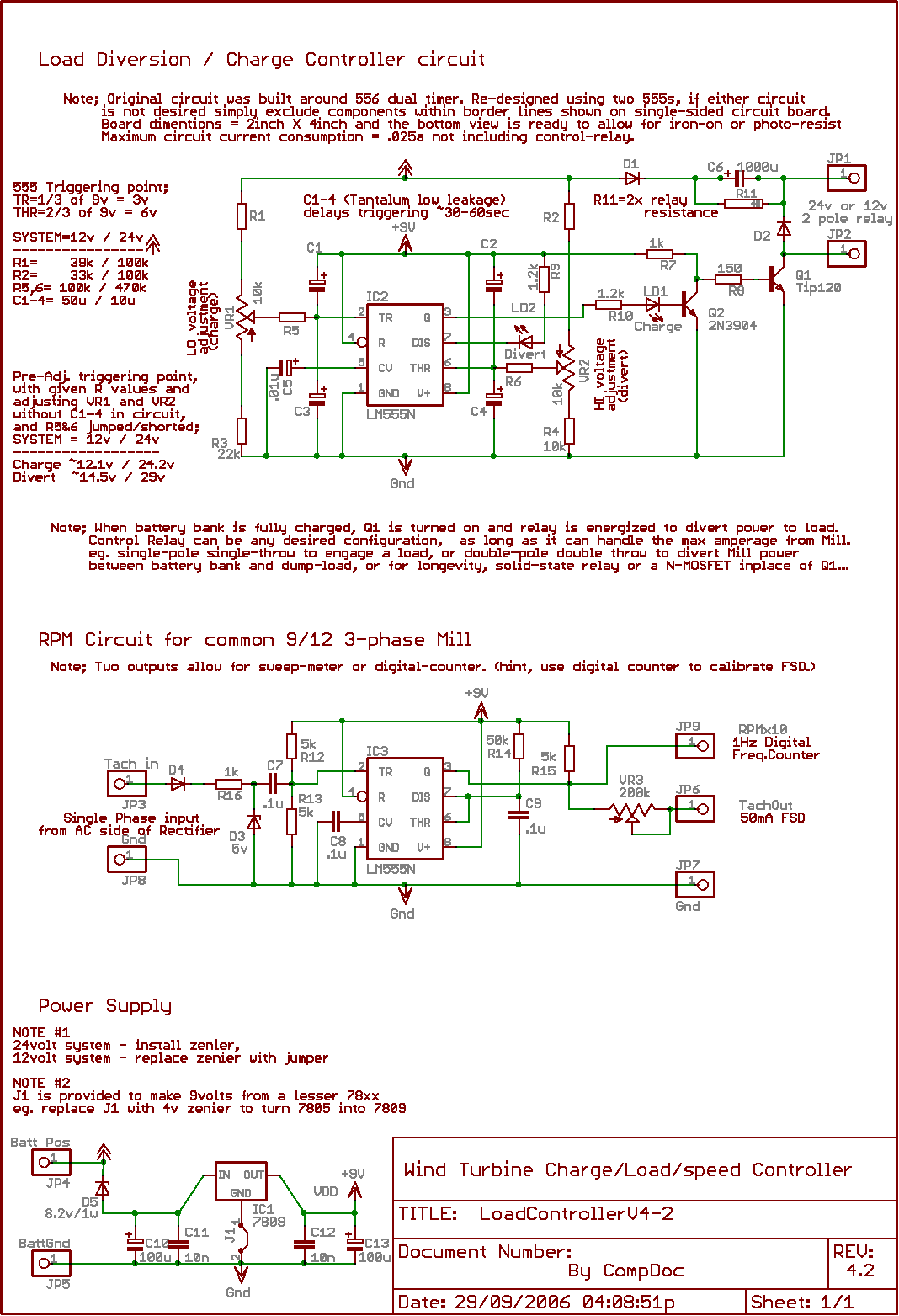
In my files you will find the simplest charge controller (that has excellent stability and reliability) that you can build for just a few dollars.  The controller also includes an optional circuit for reporting RPM/speed of the alternator.


If you decide to build this controller, you will need a suitable dump load, or preferably, a diversion circuit to a water heater... the hydro system should produce a fairly constant supply of power that would be a shame to waste.


This controller is designed to fit on a 2x4inch single sided PCB with only two jumpers, designated by square pads.  This makes it easy for beginners and DIYSers.

Hint's for adjusting the Charge-voltage and Divert-voltage (dump).  When assembling the controller, do not install C1-4 until after initial adjustments.  Make initial adjustments with trim potentiometers to desired triggering voltages at the timer pins 2 and 6 with R5 and 6 shorted with a jumper.  This will get you close to target voltages without the triggering-delay introduced by C1-4 and R5-6.  Use a good digital volt meter when making measurements.  Remove jumpers from R5 and 6 and then install capacitors to make final adjustments, pausing to allow time for the trigger-delays to expire.

Place a momentary push-button switch between Pin2 of the Controllers 555 and ground. This will allow you to force the circuit into `charge mode' on demand.


Cheers!


« Last Edit: October 06, 2006, 01:30:46 PM by CompDoc »