There's been a lot of discussion of late about led lighting. In particular about reliability (or the lack thereof).
In this thread
http://www.fieldlines.com/story/2007/4/15/205620/470
I started explaining why a single resistor is not very successful when the system is powered by lead-acid batteries.
To recap;
Led's are current operated devices. The voltage drop across them is nothing more than a practical nuisance. The ideal led would behave the same as an ideal zener diode. Below a certain voltage, they would draw no current. Above a certain voltage, they will draw as much current as the supply can deliver.
In your case, it only works because the leds are not perfect zeners, and the battery voltage just happens to be at one particular sweet spot. What happens when that battery is being charged, and the voltage is approaching 15 volts. What is your led current then?
And if resistors are bad and waste heat (energy), what do you think that red led is doing, especially if you cover it with black tape.
The correct way to power an led is with a constant current source, so that the current remains constant irrespective of battery voltage. A series resistor can approximate a constant current source over a limited range of input voltage, if the difference between battery voltage and combined led voltage is high enough.
Some worked examples;
R = E/I
E = Vbatt - Vled
I = 20mA
Vled = 3.6 volts
Vbatt = 11 to 15 volts
for one led, the resistor value at Vbatt = 11 volts is
(11 - 3.6) / 20mA = 370 ohms
when Vbatt is 15 volts, this resistor will give an led current of
(15 - 3.6) / 370 = 30.8mA
for two leds, the resistor value at Vbatt = 11 volts is
(11 - 7.2) / 20mA = 190 ohms
when Vbatt is 15 volts, this resistor will give an led current of
(15 - 7.2) / 190 = 41.1mA
You can see the trend. I leave it to the interested reader to calculate values using 3 leds.
So, to use a simple fixed resistor, we can see that the best we can do to achieve a semi constant current in the led is to use a string of one led per resistor. Not very efficient. And we still get a change of 50% in the led current between empty (20mA) and full (30.8mA).
And so we get to circuit 1.
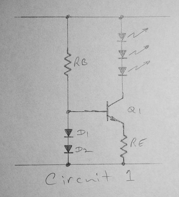
Simplifying and idealising, it works like this.
The 2 diodes drop a voltage of 1.2 volts. The transistor drops 0.6 volts across the base-emitter junction (Vbe), leaving 1.2 - 0.6 = 0.6 volts across Re. Since this voltage is obviously constant, and the resistor value is constant, the transistors emitter current (Ie) must also be constant. And since the transistors collector current (Ic) is equal to Ie, the current in the leds must also be constant.
In practice, the voltage across the 2 diodes will vary as a function of the supply voltage (google pn junction dynamic resistance if you must know more). Also, the Vbe of the transistor will vary as a function of heat. As the supply voltage goes up, the transistor drops more voltage across the collector emitter junction (Vce), hence power dissipation goes up (Vce x Ic) generating heat in the transistor. Vbe goes down as a function of temperature, approx 2mV per degree C. This can be partially mitigated by physically bonding the 2 diodes to the transistor, so the diode voltage also goes down as a function of temperature.
Expanding this circuit, we can run multiple led strings, adding just one transistor and one resistor for each additional string (see circuit 2).
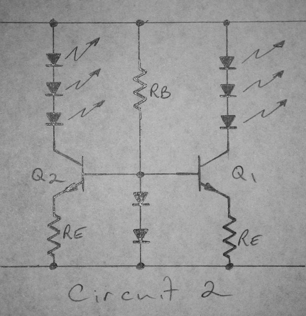
The problem here is you can't easily bond the transistors and diodes together to mitigate the thermal effects.
And so on to circuit 3.
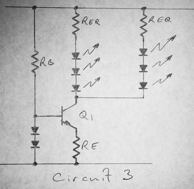
We use one transistor to deliver current to multiple led strings. We now need to add a small resistor in series with each string (Req) to equalise the leds, because they won't all have exactly the same forward voltage drop. Problem now is we have also multiplied the transistor self-heating effect, because it is passing n strings as much current.
And now to the piece-de-resistance.
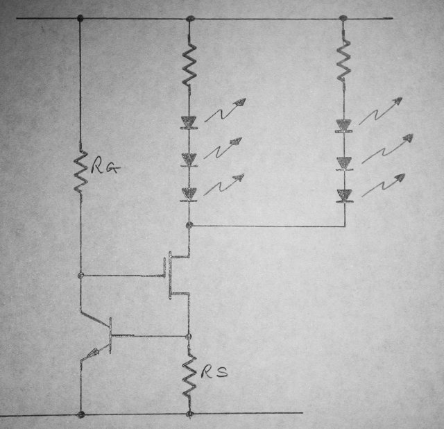
In circuit 4, we use a fet as a variable resistance element. Rg biases the fet on, current starts to flow in the fet, generating a voltage across Rs. As this voltage approaches 0.6 volts (Vbe of the transistor), the transistor starts to turn on. The transistor decreases the voltage on the gate of the fet, tending to turn it off. We now have a constant voltage across Rs (Vbe), and a constant drain current in the fet. Again, we run multiple strings of leds, each with their own little equalizing resistor (Req).
In practice, we now have the exact opposite of the previous example when it comes to heat. We bond the transistor to the fet. As the fet gets hot, the transistor Vbe decreases, so the voltage across Rs decreases, and the current through the fet decreases. We have now effectively prevented thermal runaway. There's a new concept for you, didn't mention that one before, did I?
Go back to the very first example, the simple led and series resistor. Now, instead of using an ideal led, lets use a real led. The forward voltage drop of a real led behaves exactly the same as the Vbe of the transistor, minus 2mV per degree C. What happens to the current through the led as the temperature rises? Vbatt minus Vled divided by the resistor. If Vled falls, then the current must increase, leading to more heat, therefore more current, very quickly terminal. If you have 3 leds in series with one resistor, the effect is multiplied 3 times.
Taking circuit 4 to its logical conclusion, you end up with this dimmable led circuit.
http://radiolocation.tripod.com/LEDdimmer/LEDlampDimmer.html
I have deliberately left out the switchmode variants of driving leds, so as to spare our readers the frustation of being presented with circuits too complex for any sane person to build, or IC's made of specially imported (from a galaxy far, far away) unobtainium, and/or obsoletium. This last one is copyright by me, Amanda Wynne, 2007; I just thought of that one.
In part 2 of this led master class, I will present some actual examples of these circuits, complete with component values and performance data. I bread-boarded circuit 4 today, and it is sweet. 3 red leds, 10mA at 8 volts, 11mA at 30 volts.
Till next week.
Amanda
