Led master class; pt 4<p>
If you haven't already done so, I suggest you read the previous instalments here;<p>
http://www.fieldlines.com/story/2007/4/20/95351/1614http://www.fieldlines.com/story/2007/4/26/82929/6080http://www.fieldlines.com/story/2007/5/1/74856/25992<p>
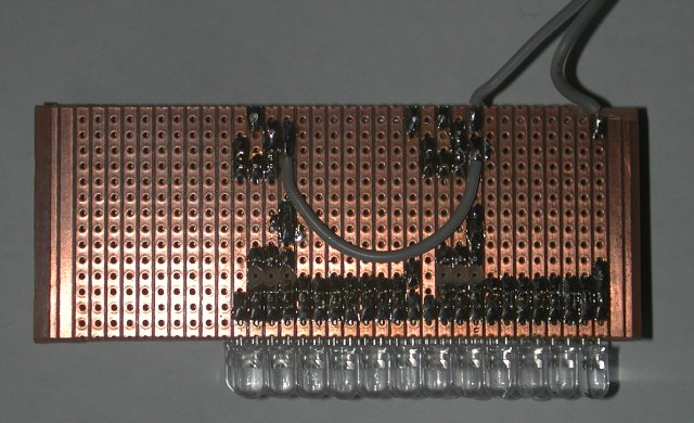
As mentioned at the end of part 3, this is an example of how I built circuit 4. I've yet to mount it in a proper enclosure.
The photos should be fairly self explanatory. Each board has 2 circuits. Each circuit has one string of 6 leds, and runs off 24 volts.
Note that it is necessary to file the ridge off the base of the leds to mount them this close together on veroboard.
The fet (2n7000) and bipolar transistor (BC547) are physically bonded for thermal control.
The 3 boards have wire links joining them together to distribute power.
The lego box was thrown together hastily to protect the unit when I took it to BTHumble's bonfire bash back in May, where it was used as a hand-held light to illuminate the BBQ while the food was cooked. This thing is so bright, it is impossible to look at directly, even from 30 meters away.<p>
Temperature:
Even in an open enclosure like this lego box, the operating temperature in the middle of the 36 leds is 25 deg C above ambient.
Running off a bench power supply at 24.0 volts, and an ambient temperature of 17.5 deg C, the current when first switched on was 99.6mA, dropping to 90mA after about 15 mins of operation.
<p><p>

<p>
<p>

<p>

<p>
I added 100nF bypass capacitors across the npn transistors (collector-emitter) for stability.<p>
The next instalment is an extension of circuit 4, and adds a phototransistor to make a night-light. This time it is actually finished off and mounted in an enclosure. Hopefully it won't take me another 6 months to get it published.<p>
Amanda<p>
PS: note to board admin.
It seems the add photo function is missing when creating a new story.
