Author Topic: Basic generator to battery question  (Read 18012 times)

0 Members and 1 Guest are viewing this topic.

CmeBREW

  • Hero Member
  • *****
  • Posts: 615
Basic generator to battery question
« on: January 14, 2007, 09:07:29 PM »
Greetings all: I have a basic PMG generator to battery question. It has probably been covered before, but i could not find it- -so please forgive me if it has. A short simple answer is greatly appreciated.


I just made this small PMG alternator that does 10-20 watts max. at 300-500 rpm.(shown below)  The magnets are tiny (3/8" diam x 1/2"deep) is why there is so little power. (live and learn) -The 20 watt max i get is while shorting it through my ammeter to get a reading. However, when I hook it to my 2/ 12V marine batteries (hooked parallel), I only can get 8 watts going in. Is it somehow possible to get the full 20 Watts going into the batteries. Unfortunetly, I cannot hook half the generator coils in parallel to get twice the amps, because it would take too strong a wind to reach cuttin voltage. (only getting about 10 volts @500rpm with coils hooked in parallel)

Is there anything I can do to get more of the maximum amps out of the 12 coils hooked in series?  

I also have this same problem with a permenent magnet treadmill motor I was testing. I get 2or3 times the amps shorted thru my ammeter.    -Any help is super appreciated.


This is my first PMG. Not much power but at least it works. It does 18vac/16vdc @500rpm and 13vdc(cut in) @300 rmp.

« Last Edit: January 14, 2007, 09:07:29 PM by (unknown) »

Flux

  • Super Hero Member Plus
  • *******
  • Posts: 6275
Re: Basic generator to battery question
« Reply #1 on: January 14, 2007, 02:15:50 PM »
You don't seem to understand the concept of power.


You get amps into a short circuit, but there is no power. Power is the product of amps and volts. You will never get the short circuit current into any form of load at a given speed.


Your true power is the amps into the battery x battery volts. With a tiny alternator you have to accept that you will need to run it at high speed to do anything. 500rpm is not such a high speed for a small windmill with an output of 20W.

Flux

« Last Edit: January 14, 2007, 02:15:50 PM by Flux »

CmeBREW

  • Hero Member
  • *****
  • Posts: 615
Re: Basic generator to battery question
« Reply #2 on: January 14, 2007, 03:11:13 PM »
Thanks Flux,

  I think I see what you are saying, but wouldn't I get more amps being pulled out of the generator if I got 2 more batteries and hooked them up in parallel with the 2 I have. Wouldn't this lower the resistance and 'pull' more amps out of the generator?

So are you saying, there is no way to 'pull' more amps out of this alternator?Believe it or not, I had 2 years of Electricity when I was younger, but I must have been either sleeping in class or looking at girls.   Am I right, or did I simply dream that this is possible?  -Thanks
« Last Edit: January 14, 2007, 03:11:13 PM by CmeBREW »

CmeBREW

  • Hero Member
  • *****
  • Posts: 615
Re: Basic generator to battery question
« Reply #3 on: January 14, 2007, 03:23:42 PM »
I mean 2 years HIGH SCHOOL Electricity, NOT college. What I'm saying is I really don't know much of anything on the subject!
« Last Edit: January 14, 2007, 03:23:42 PM by CmeBREW »

RP

  • Hero Member
  • *****
  • Posts: 722
  • A dog with novelty teeth. What could go wrong?
Re: Basic generator to battery question
« Reply #4 on: January 14, 2007, 04:29:40 PM »
Unfortuneately the generator can't push anything into the batteries until the output voltage is higher than the battery voltage.  You might get more if you were charing say a 6 volt battery but a 6 volt battery isn't good for much.


Can you tell us more about the alternator: single phase/3 phase, and how it's wired to the rectifiers?  There may be something that can be done there...

« Last Edit: January 14, 2007, 04:29:40 PM by RP »

CmeBREW

  • Hero Member
  • *****
  • Posts: 615
Re: Basic generator to battery question
« Reply #5 on: January 14, 2007, 05:20:29 PM »
Thanks RP,

   By the photo you can see it is a simple single phase 12 pole(magnet) 12 coil (24ga./ 100 loops each) Alternator. It is an Alternator (AC) , so it is hooked to a simple 25 amp bridge rectifier, ac in , dc out. The magnets are simply too small. The air gap is as small as it can be. (about 5/16") I was just hoping there was a way to pull more amps out of it while keeping the rpm down to around 500. But since this is evidently impossible, i will go ahead as flux suggjested and wire the coils in parallel (reducing the resistance/twice the amps/half the volts) and hope my 4 ft. rotor will turn over 700rpm in order to reach cut-in voltage (13volts). I don't really know what rpm a 4 foot genny can reach. Like I said this is my first prototype. Mine should probably be even less than 4 feet. I don't really know. (I'm still beginner)  -Can a 4 ft. alternator reach over 7or 800 rpm?            


« Last Edit: January 14, 2007, 05:20:29 PM by CmeBREW »

RP

  • Hero Member
  • *****
  • Posts: 722
  • A dog with novelty teeth. What could go wrong?
Re: Basic generator to battery question
« Reply #6 on: January 14, 2007, 06:35:05 PM »
Well a 4 foot diameter set of blades with a TSR of 7 would get you 735 rpm in a 15mph wind.  


A 3 ft diameter TSR 7 set would get you 719 rpm in an 11mph wind.


Take the wind speed in mph/60=mpm (miles/minute)

mpm*5280=fpm (feet/minute)

fpm*TSR (Tip Speed Ratio)=tip speed in feet/minute


Tip speed/(diameter in feet X PI)=revolutions/minute.


Takes just a few moments to set it up in a spreadsheet and plug in new numbers.

« Last Edit: January 14, 2007, 06:35:05 PM by RP »

CmeBREW

  • Hero Member
  • *****
  • Posts: 615
Re: Basic generator to battery question
« Reply #7 on: January 14, 2007, 07:05:18 PM »
Thanks RP,

    That helps me some. I don't really know too much about 'tip speed ratios" yet. No doubt something i'll need to learn. I will make a 4ft pine wood rotor and see what happens. After all thats the fun part. I would think by now someone could have figured out some kind of electronic device that could convert most of this lower voltage power (under the 'cut it' voltage that is) and lift it up with capacitors or something and a high speed triac switching circuit of some sort.

Anyway thanks for the help!
« Last Edit: January 14, 2007, 07:05:18 PM by CmeBREW »

CmeBREW

  • Hero Member
  • *****
  • Posts: 615
Re: Basic generator to battery question
« Reply #8 on: January 14, 2007, 09:17:10 PM »
Thanks Flux:


You said:

"You get amps into a short circuit, but there is no power. Power is the product of amps and volts. You will never get the short circuit current into any form of load at a given speed."


   Actually now I don't fully understand your first couple of sentences after a did alittle test with my small alternater. I hooked it up to a treadmill motor as a load and with my alterntor running at 500 rpm the ammeter showed only .25 amps@ 16 volts (4 watts). The treadmill is spinning pretty fast with this, and so I then put my foot on the treadmill shaft and the current from the alternator goes way up to 1.2 amps@15 volts (18 watts) at the same 500 rpm, and I can't even hold back the shaft from spinning.(Is that not POWER) - So the power IS there in the small alternator, I just need to figure out (if it's possible) how to get that power potential into the batteries. Do they make very low resistance batteries? I also did another test with my two batteries. The alternator put about 10% more power into 2 batts hooked in parallel than just one battery by itself.  I hate to not use over 75% of the power potential in the alternator. Of course I am still just a beginner trying to learn all these many 'trade offs' involved with windmills. It is very intriging and mind boggling at the same time.  -Thanks for trying to help friends!  

« Last Edit: January 14, 2007, 09:17:10 PM by CmeBREW »

willib

  • SuperHero Member
  • ******
  • Posts: 2414
  • Country: us
Re: Basic generator to battery question
« Reply #9 on: January 14, 2007, 10:07:39 PM »
Nice job on the stator!

if you had larger mags ... well you know

shame its wired in series , it would make a nice three phase stator.

keep up the good work!
« Last Edit: January 14, 2007, 10:07:39 PM by willib »
Carpe Ventum (Seize the Wind)

RP

  • Hero Member
  • *****
  • Posts: 722
  • A dog with novelty teeth. What could go wrong?
Re: Basic generator to battery question
« Reply #10 on: January 14, 2007, 10:36:01 PM »
What you want is called a boost convertor.  A couple inches down from the upper right side of the page is "Google search the board".  Use that to search for stories on it here.


It's not a simple solution though.  Another alternative is to use a DC to DC convertor but in either case you lose some energy in the conversion.

« Last Edit: January 14, 2007, 10:36:01 PM by RP »

ghurd

  • Super Hero Member Plus
  • *******
  • Posts: 8059
Re: Basic generator to battery question
« Reply #11 on: January 15, 2007, 12:24:59 AM »
The Math.  A x V = W, (at the same time)

so 1,000A x 0V = 0 Watts, (short circuit)

or 0A x 1,000V = 0 Watts. (open volts)


The 10% could be related to a change in the battery's increased voltage under charge, and a few other things.  I wouldn't worry about that.

If the battery capacity is doubled, the battery self discharge is also doubled.

It's probably not worth doubling the batteries.


The treadmill motor I'm not clear about.  The volts and amps were measured at the same time?  Then yes, it is making 4W and 18W.

There are a lot of different treadmill motors, but you may be running into some problems by using a motor as a test load.  If you don't like testing into a battery, I'd suggest trying a 55W 12V light bulb, or maybe 2 #1156 tail light bulbs in parallel.

G-

« Last Edit: January 15, 2007, 12:24:59 AM by ghurd »
www.ghurd.info<<<-----Information on my Controller

Flux

  • Super Hero Member Plus
  • *******
  • Posts: 6275
Re: Basic generator to battery question
« Reply #12 on: January 15, 2007, 01:29:46 AM »
Now you have given a bit more information I can help a bit more.


You saw 16v at 500 rpm with virtually no load, so your cut in at 12v will be at 12/16 x 500 = 375 rpm. ( say 400 rpm for a reasonably charged battery).


You get 1.2A at 15v, so you would get that into a fully charged battery when equalising.


You are not much above your cut in point, but power will increase as you take the speed over 500rpm so there is nothing to worry about. Don't reconnect it for double the speed, it is fine for a 4 ft prop with cut in at 375 rpm if you make a prop with tsr6 or so.


In higher winds the speed will go up to over 1000rpm without much trouble and your problem is more likely going to be preventing it burning out rather than getting enough power.


Battery resistance is so low as to make no difference, the gain you saw with 2 batteries in parallel was due to a slight drop in voltage as Ghurd said, nothing to do with resistance.


Take the trouble to learn about props and make something with a tsr of 6 or 7 and it will do far more than your expected 20W.


Don't get too confused about that motor you used as a load, the motor will only take the power it needs to do what it has to. As you load it, it takes more power to supply the load ( foot warmer ) If you completely stalled the motor you would see more amps at a low voltage.


Flux

« Last Edit: January 15, 2007, 01:29:46 AM by Flux »

gotwind2

  • Sr. Member
  • ****
  • Posts: 383
  • ben[at]gotwind.org
    • Gotwind - The Renewable Energy Resource
Re: Basic generator to battery question
« Reply #13 on: January 15, 2007, 02:35:32 PM »
Can't really help with the figures, but this looks like a great start to a mini axial flux PMG/PMA - Keep going, your work is admirable.


Ben

www.gotwind.org

« Last Edit: January 15, 2007, 02:35:32 PM by gotwind2 »

CmeBREW

  • Hero Member
  • *****
  • Posts: 615
Re: Basic generator to battery question
« Reply #14 on: January 15, 2007, 07:46:01 PM »
Thanks for the comments and compliments friends! You gave me alot of Info. to chew on. Yes this is a down-sized single phase dual rotor axial flux PMA copied in principle from the big boys. I thought I better make a small one first to learn things and then make a bigger one. And I HAVE learned ALOT. I am already working on the bigger one- hopes it will do up to 500watts and 8ft rotor.(I got about 6 lbs N40 mags compared to the 7oz. of mags on this little Pete Prototype)

Nevertheless, I was incorrect on a figure last night. As Ghurd pointed out the voltage did drop more than I thought when testing on the treadmill motor. I failed to take both measurements at same time. Today i did, and the more pressure I put on the shaft of the treadmill the more the amps when up, but the more the voltage went down. As flux said, when I stopped the treadmill completely with my foot, I got about 1.2 amps but only 6 volts. The voltage dropped from 18 to 6. It is just so very difficult to believe that only 8 or 10 watts is causing that much torque in the treadmill motor! It feels like about 50 watts! I apologise for the mistake.

When I tested into the batteries last night my batts were fully charged. I don't know if this makes a difference. I believe I only got 8 watts @500rpm. I took some energy out of the batteries (about 5-10%)- and then did test--The alternator was putting 8.5 watts back in them. I will try to discharge more and do more tests.

I will do what Flux said with making the 3 blades (4ft) at about 7tsr and see what happens soon. I already got the pole up. I will make it furl at about 20 or 30 watts , if it'll go that high. Wait and see. Your comments have helped me at this point. I really wanted to get this little prototype in the air cause my bigger dual rotor alternator may not be ready for a couple of months and the wind has been AWESOME around here in Ohio this winter. (but almost nothing in summer!)

Anyway, here are a few more pics of this tiny prototype. I took many pictures of the whole process. These are just a few. Later I will display them all and the processes, including my bigger downwind alternator, to possibly help others and  give some ideas.       -Thanks guys


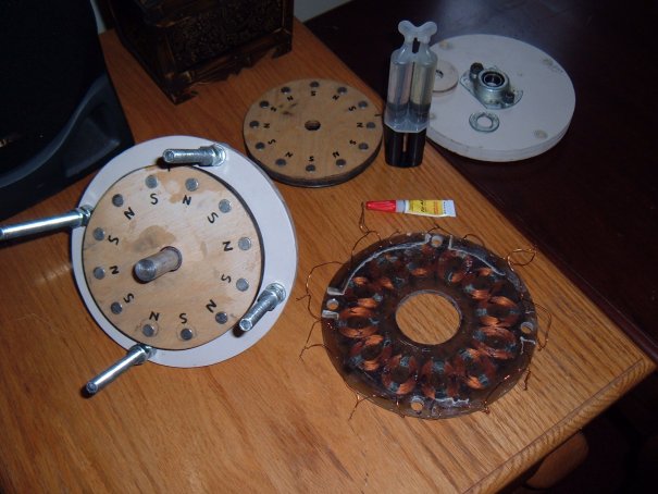
The Stator was pretty easy to make. I simply used plywood-cut out the radius, and used wax paper inbetween. It is perfectly flat and is 1/4th in thick. Overall magnet to magnet air gap is about 5/16".


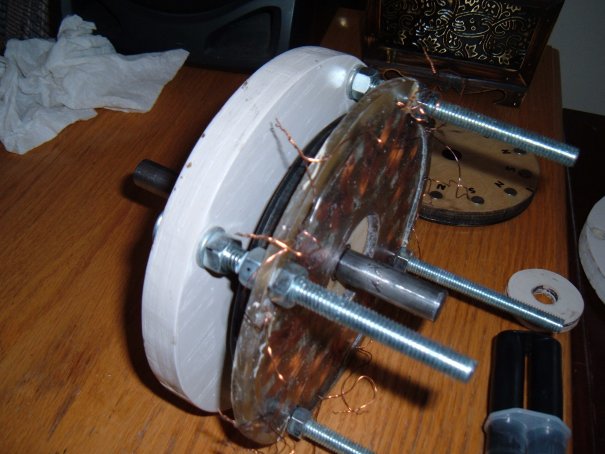
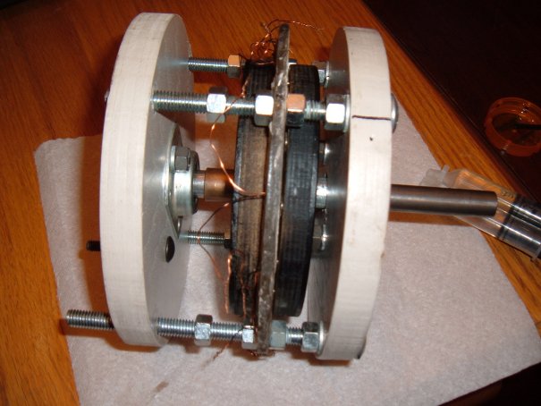
The construction is very simple. The front and back is 3/4in. plywood painted w/2 coated exterior paint (will be 3), 5/8" ball bearings and rod. I used a piece of metal (electrical) conduit about 1.25" to go over the rod to the front bearing. I then ground out a couple of 7/16" washers with my dremel tool to fit tightly over the 5/8" rod.


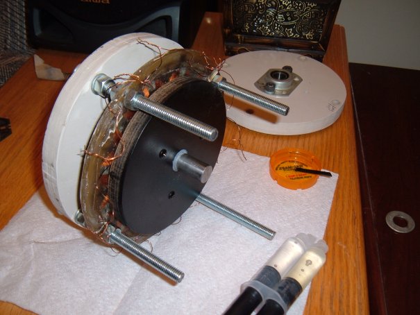
I actually don't know which photo I'm commenting on. Anyway the magnet rotors are about 6" dia. -made with 1/2" baltic birch plywood and a 1/8" think steel back.(painted black) You could probably up size a bit and use a couple of 7.25" circular saw blades (plywood type-NOT carbide) for this. Just grind the sharp HHS tips off with your grinder.(of course you would have to heat treat the metal with your propane torch where you want to drill any holes thru- but thats easy and quick to do)


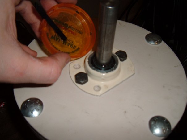
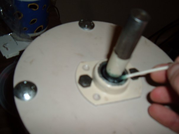
Lastly, I sealed the front bearing with 5min. epoxy to make it waterproof. First, I used silicon caulk to seal behind the bearings and bolts. Before I poured the epoxy, I put grease very carefully on the shaft and on the crease that goes around and around near the shaft. It starts setting in just a few minutes, so i took the masking tape off before it set - but be careful not to turn the shaft. Obviously, if epoxy goes down into the bearing, it is ruined and you've got a quick headache. But it worked for me like a charm. The shaft 'broke free' from the hardened epoxy very easily.


Oh -I forgot to mention that I EPOXY the magnet rotors to the shaft. Believe it or not, If you use a 5/8" fortsner brill bit, this makes a VERY strong bond. You would have to break it off with a hammer- and it would break the wood not the bond. (i know cause i had to do this earlier to redo the rotor mag set up)

So, to make a short story long, I'm going to use silicon caulk and wrap sheet metal around the front and back and screw it at bottom, and epoxy the 4' (3 pine 2x4 blades) to the shaft and i'm good to go!  I will publish the results soon. Thanks again.
« Last Edit: January 15, 2007, 07:46:01 PM by CmeBREW »

ghurd

  • Super Hero Member Plus
  • *******
  • Posts: 8059
Re: Basic generator to battery question
« Reply #15 on: January 15, 2007, 09:26:42 PM »
That worked out quite nice!


An idea you may or may not like...

It LOOKS like there is space in the coil holes for a complete 2nd set of the same size magnets. And the rotors look like the 2nd set would fit pretty well compared to the coils.

So drill holes and add more magnets, very nearly touching the first magnets, on the inside diameter (between the existing magnets and the polarity markers).


Even if it's not a perfect fit, the open volts will increase probably enough to use the coils paralleled, the resistance will then be halved, and the output power will increase.

You went this far. Might be worth a couple bucks for more magnets?

G-

« Last Edit: January 15, 2007, 09:26:42 PM by ghurd »
www.ghurd.info<<<-----Information on my Controller

willib

  • SuperHero Member
  • ******
  • Posts: 2414
  • Country: us
Re: Basic generator to battery question
« Reply #16 on: January 15, 2007, 09:45:06 PM »
http://www.otherpower.com/images/scimages/3274/algenerator1I.jpg

where did you find those bearing holders in this photo?


i have to comment on the discussion of 0 Volts dropped , when measuring current with an ammeter, because thats just not the case.

there certainly is voltage dropped when reading current through an ammeter if you check it with a voltmeter ,you will see.

the whole discussion on shunt resistors , a few days ago is proof that even with an increadably large shunt there is still voltage dropped across it, albeit very small ,but it is there , it has to be.

/rant

« Last Edit: January 15, 2007, 09:45:06 PM by willib »
Carpe Ventum (Seize the Wind)

TomW

  • Super Hero Member Plus
  • *******
  • Posts: 5130
  • Country: us
Re: Basic generator to battery question
« Reply #17 on: January 15, 2007, 09:53:31 PM »
Yeah there is a voltage drop, typically 50 mv. [.050V] on many commercial shunts full current rating so even with 100 amps on a "short" test thats a whopping 5 watts. Not to be argumentative but thats hardly significant.


Just had to point out that sometimes "none" can mean "not a significant amount"


Cheers.


TomW

« Last Edit: January 15, 2007, 09:53:31 PM by TomW »

willib

  • SuperHero Member
  • ******
  • Posts: 2414
  • Country: us
Re: Basic generator to battery question
« Reply #18 on: January 15, 2007, 10:30:44 PM »
Tom i think you missed the point i was making

the point was'nt the amount of power dissipated in a shunt.

the point was the OP was measuring the power out of his gen, with a resistance (Ammeter),and it was stated that there was 0 volts across a short , i'm not shure there is such a thing as a direct short, because there will allways be a voltage dropped across any resistor, carring current.
« Last Edit: January 15, 2007, 10:30:44 PM by willib »
Carpe Ventum (Seize the Wind)

willib

  • SuperHero Member
  • ******
  • Posts: 2414
  • Country: us
Re: Basic generator to battery question
« Reply #19 on: January 16, 2007, 07:42:06 AM »
one more thing , since you still have all the coil ends exposed you can wire it in star ,and add four more poles , and build a 16pole 12coil three phase machine

because the stator you have constructed IS a three phase stator , not a single phase

you would benefit from knowing the difference when you build your next machine

« Last Edit: January 16, 2007, 07:42:06 AM by willib »
Carpe Ventum (Seize the Wind)

CmeBREW

  • Hero Member
  • *****
  • Posts: 615
Re: Basic generator to battery question
« Reply #20 on: January 16, 2007, 08:04:09 AM »
Thanks Ghurd,

    Your are absolutely right- very perceptive.  I had realized that I could have put an entire second set of magnets in, and it would have probably tripled the power cause there would have been two magnets on each coil. But i didn't want to put anymore money into this prototype. Its too late now- there epoxied in! I have learned the basic principles now--and I now know how easy and better it is to do 3-phase. (looks like about 30-50% more power per revolution using the same amount of magnets).  Those tiny magnets in there are actually 1/8" thick STACKED magnets to equal 1/2" deep.(4 mags stacked on top of each other) This of course is yet another little mistake I made since there is less power with stacking magnets. I am finally motivated to finish and get this thing in the air now. One good thing about it is that it starts up extremely easy, and since there is almost no resistance, it should reach cut in voltage (about 300rpm) in a very low wind.  The cut-in amprage, though, is only about .16amp@13 volts.(2watts)  Nevertheless, it will be interesting to see what it will do, especially since it should charge day and night, the majority of the time. -Thanks  
« Last Edit: January 16, 2007, 08:04:09 AM by CmeBREW »

CmeBREW

  • Hero Member
  • *****
  • Posts: 615
Re: Basic generator to battery question
« Reply #21 on: January 16, 2007, 08:36:08 AM »
Actually, it is single phase- I don't believe 'all the kings men' could convert it to 3-phase now.
« Last Edit: January 16, 2007, 08:36:08 AM by CmeBREW »

CmeBREW

  • Hero Member
  • *****
  • Posts: 615
Re: Basic generator to battery question
« Reply #22 on: January 16, 2007, 08:41:33 AM »
Actually, the bearings came with those metal holders. I got em at a surplus store around here for $3 ea.
« Last Edit: January 16, 2007, 08:41:33 AM by CmeBREW »

stop4stuff

  • Sr. Member
  • ****
  • Posts: 263
Re:
« Reply #23 on: January 16, 2007, 11:37:42 AM »
CmeBREW...


Unless your 12 coils are overlapping, you do not have a single phase alt, you have a pair of magnet rotors with 12 poles and 12 coils that look like there's a fair amount of cancelation, hence your poor output.


Looking at your pictures, do you have this setup?;


Magnet & coil spacing is important to maximise output, for 12 poles the following are the norm;


  • 6 coils, centers spaced 60 degrees, legs & center hole same size as mag dia (single phase)
  • 12 coils, centers spaced 30 degrees, legs & center hole same size as mag dia with overlapping legs (1, 2 or 4 phase)
  • 9 coils, centers spaced 40 degrees, legs & center hole same size as mag dia, touching legs (3 phase)
  • 36 coils (3 phase)... difficult to explain, see; Windstuff Ed's 3 phase turbine kit or http://www.fieldlines.com/story/2004/5/26/15451/3307 for an example.


As willb says, you have a 3 phase stator suited to 16 pole rotors;

(exact same stator layout with 12 coils as the image above)


paul

« Last Edit: January 16, 2007, 11:37:42 AM by stop4stuff »

CmeBREW

  • Hero Member
  • *****
  • Posts: 615
Re:
« Reply #24 on: January 16, 2007, 02:26:46 PM »
Hello stop4stuff:

    Yes, your first diagram is EXACTLY what I have. 12 magnets exactly spaced in the middle of each of the 12 coils as they go around. But my coils do not overlap-if i understand you right. I already knew that If I wanted to completely re-make new magnet rotors I could make a 3-phase alternator with 16 poles. Now I see what willb was saying. But  I don't want to re-make the rotors! I thought my alternator was a single phase since all 12 mags come accross each coil leg of each coil at the same time. Hope I didn't misunderstand that. Originally, the magnets WERE suppose to be 3/4" diam. , which is the center hole of each coil, but I was tring something different and well... - it didn't work, and so this is what I wound up with.(difficult to explain)

However, your first diagram is exactly what I wound up with. You even drew the magnets smaller as they are. Today I hooked a faster drill to the alternator and it is doing much more power at a higher RPM. (as Flux said) I'm getting over 30 watts at somewhere around 800-1200 rpm.(only rough guessing) The drill seems to be doing this fairly easy.(of course the drill is rated for 3100rpm, so i am just guessing where 1000rpm is.)

If you think I've done the layout totally wrong, please let me know. Thanks for the diagrams.  
« Last Edit: January 16, 2007, 02:26:46 PM by CmeBREW »

Flux

  • Super Hero Member Plus
  • *******
  • Posts: 6275
Re:
« Reply #25 on: January 16, 2007, 02:40:56 PM »
What you have done is perfectly logical, you seem to have set out to make it single phase and have done so in a perfectly satisfactory way. You also seem to understand the 16 pole 12 coil 3 phase set up.


One thing I am not sure about, are the magnets on steel plates or just into plywood.


If just in plywood then you are loosing a lot of potential output.


Flux

« Last Edit: January 16, 2007, 02:40:56 PM by Flux »

CmeBREW

  • Hero Member
  • *****
  • Posts: 615
Re:
« Reply #26 on: January 16, 2007, 03:21:34 PM »
Thanks Flux,

    For a minute there I feared I'm even dumber than I thought. I thought I knew the basic principle of single phase. I don't see any cancellation myself. There are no similar poles on a same coil. But at the same time, i'm only getting one magnet on only one leg of each coil, which is less power than if I had used the 3/4" diam. magnets which would

have got me about 1/4th (or more)of the next magnet on the same coil.(the opposite leg/side of one coil) Which would have meant more power. Thats alittle difficult to explain. Anyway I appreciate the 3-phase diagram of the 16 pole/12 coil , cause that is the set-up of the bigger alternator I am currently making using 7/8" x 7/8" N40 mags. (16 mags on each rotor/ and 12 coils.)

The answer to your question is yes, Each pole is 3/8"dia. x 1/2" deep. So they go thru the 1/2" plywood and stick to the 1/8" steel plate. In fact, Thats why I had to redo both the rotors, so they would be stronger flux accumulating on the steel plates.    -Thanks
« Last Edit: January 16, 2007, 03:21:34 PM by CmeBREW »

willib

  • SuperHero Member
  • ******
  • Posts: 2414
  • Country: us
Re:
« Reply #27 on: January 16, 2007, 04:03:55 PM »
I dont mean to belabor the single phase point

 a true single phase has gaps between coils ,unlike your potential three phase stator.

the single phase has a cogging effect because each magnet passes over a coil

leg at the same time. Unlike a three phase machine which distributes the load

evenly and is preferable to single phase


http://www.otherpower.com/images/scimages/2965/single_phase.JPG


http://www.otherpower.com/images/scimages/2965/single_phase2.JPG

« Last Edit: January 16, 2007, 04:03:55 PM by willib »
Carpe Ventum (Seize the Wind)

CmeBREW

  • Hero Member
  • *****
  • Posts: 615
Re:
« Reply #28 on: January 16, 2007, 05:36:14 PM »
Thanks Willib,

   Thats certainly true. But it must be much less noticable with a smaller, high rpm alternator like mine- cause it sure seems quite smooth even at over 2000rpm. (now I'm getting over 40 watts into the batteries, but of course thats WAY too fast for my blades) The main reason I did single phase is because I didn't understand (4 certain) 3-phase at the time. But now I do.   -Thanks for everyones' help!
« Last Edit: January 16, 2007, 05:36:14 PM by CmeBREW »

ghurd

  • Super Hero Member Plus
  • *******
  • Posts: 8059
Re: Basic generator to battery question
« Reply #29 on: January 17, 2007, 06:47:32 AM »
I was thinking a forester(?) bit down to the iron, then epoxy the neos into the hole.

Only $20 for the neos, but maybe you mean the WHOLE PMA is epoxied together?

http://www.forcefieldmagnets.com/catalog/product_info.php?cPath=23_37&products_id=32

« Last Edit: January 17, 2007, 06:47:32 AM by ghurd »
www.ghurd.info<<<-----Information on my Controller

electrondady1

  • SuperHero Member
  • ******
  • Posts: 3120
  • Country: ca
Re:
« Reply #30 on: January 17, 2007, 09:36:13 PM »
congratulations on forming a functional generator first time out of the gate.

i think your were wise to make it single phase. there is no point in forming a 3 phase stator if the output is less than a useful voltage.
« Last Edit: January 17, 2007, 09:36:13 PM by electrondady1 »

derekisastro

  • Newbie
  • *
  • Posts: 6
  • Country: us
Re:
« Reply #31 on: July 29, 2019, 07:03:52 PM »
I dont mean to belabor the single phase point

 ... each magnet passes over a coil

leg at the same time ...
Pardon my ignorance ... but isn't this exactly what he has? Every coil passes over a magnet at exactly the same time ... all his coils are in exactly the same phase yes?

CraigM

  • Full Member
  • ***
  • Posts: 205
  • Country: us
Re: Single Phase
« Reply #32 on: July 29, 2019, 09:26:09 PM »
Hello derekisastro,

Short answer, yes.

Single phase is when all coils are linked in series. The drawing below shows 5 coils and 10 poles. All coils will see N then S then N and so on... change from N to S is what creates emf (moving electrons) through the coil wire. The up and down AC sine wave is the result of the fluctuating N to S to N poles the coil is seeing. In this type of arrangement all coils are wound in the same direction, either clockwise or counterclockwise... as long as they are all the same. All coils see N at the same time and then all see S at the same time.


Single phase can also be done (and much more likely to see it this way) with the same number of poles (magnets) as there are coils. Example; 10 magnets, 10 coils. In this arrangement all coils are still connected in series but 5 of the coils will see N while at the same time 5 of the coils will see S. With this arrangement every other coil needs to be wound in the opposite direction. Five of the coils will be wound clockwise while the other five are wound counterclockwise.

So yes, you've got it.

Regards,
CM
Brain engaged in Absorption Charge Mode... please wait, this may take awhile.