This is just an opinion, and I am throwing this together in a hurry, make sure you do your homework so you don't burn your house down.
The way I see it you have several runs:
Panel to Mppt charge controller;
150 watt panel, if one assumes a maximum power rating at 24V for your 24V panel
(even though actually it should be a bit higher and therefore be fewer amps) then the
maximum amps would be about 150Watts/24 Volts, or 6.25 Amps. If you plan to add more panels later, you should not calculate this run for the 150 Watts, but the ultimate capacity that you plan to install. I fused my solar panel wire runs on the roof with a fuse that is sized over the panels maximum amps prior to combining parallel strings. I also fused the main run down to my basement.
Here is how I combined the strings:
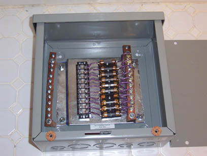
It is a simple box that I threw together for my system. Commercial versions are now available as well.
Mppt charge controller to battery;
Your system is only 150 Watts right now, but as a matter of course, I would put a transmission line in place that is capable of handling the maximum output of the Mppt controller, and I would fuse it at the battery end. Short circuiting a wire from a battery bank without a fuse in place can heat a wire red hot or throw sparks which can start a fire. The calculation for the amps would be the Watts / Volts, where the Watts are the maximum watts of the Mppt Controller.
battery to inverter
This is the big conductor. You have a 2500 Watt inverter pulling off of a 12V battery. Your inverter probably has a surge capacity as well. I would look at its maximum amp draw from the manual first. Absent that, I would size the wire for at least one and a half times its rated power. 3750 watts / 12V = 312.5 Amps.
Again, regardless of the switch, fusing, or controller on the inverter
I would put a fuse at the battery side. To not do so would be dangerous.
A slow blow fuse here is probably a good idea as most inverters
have sizable capacitors that charge up and draw a lot of amps when first connected.
Battery to Battery interconnects
This should be sized to handle the largest current to or from the battery bank. Since I fuse all wires from a battery bank, I make sure that the interconnects can handle more than the combined values of the fuses. The fuses have to be the weak links.
Here is an example of one of many wire size tables available on the web:
http://www.bnoack.com/index.html?http&&&www.bnoack.com/data/wire-resistance.html
This looks about like what I recall from reading the NEC.
Another one is at:
http://www.powerstream.com/Wire_Size.htm
it appears to be rather conservative on the maximum amps for transmission. Conservative is good.
Just because someone posts something on the Web, doesn't mean it is correct. Oversizing the conductors adds cost, but reduces resistance losses, especially in longer runs. Always make sure that the fuse is the weak link. A blown fuse generally is no big deal. A melted or blown wire, or a fire is a much bigger
problem.
Here is a wire resistance calculator that I wrote and posted here a while back for individual copper conductors:
http://www.otherpower.com/images/scimages/742/WIRECALC.exe
It is in VB and runs on Windows only, sorry if you are using another os )-:
You can use it to estimate your power losses for different runs.
