Author Topic: 36V Lester Matic Charger???  (Read 9393 times)

0 Members and 1 Guest are viewing this topic.

FrankG

  • Full Member
  • ***
  • Posts: 121
36V Lester Matic Charger???
« on: August 27, 2007, 11:48:11 AM »
Hey all!!!


I have a question about a Lester-Matic 36V/25Amp charger, that is part of an EV project that I'm currently working on.


I have 3 (three) 12V Marine batteries in series in the EV, The Lester is a very simplistic charger that uses a mechanical timer to disengage the charger (larger transformer, 2 diodes and a metal oval shaped capacitor). It appears that the Lest was hard wired to the original battery bank, so I've done the same.


My charging regime is run the Lester until I hit about 12.25 to 12.5V per battery and then I finish off the individual batteries with a Smart Charger at 2Amps. This is to Baby the batteries (that are new and represent real cash (to me)...


What I found is that once charged, if the EV sits for over a day or two the batteries are way down (below 10V each).


Is it possible that the Lester is loading the battery bank??? I can only see this if one of the diodes was shot, but then it shouldn't be working as a charger...


Also the Lester is generating a lot of heat during the charge cycle (warm enough to touch the case, but noticably hot)... My thought is that I could replace the 2 diodes with a pair of 25AMP full wave rectifiers wired in parallel and heatsinked to the same aluminum sink (to keep them at the same operating temp).


The bridge rectifiers that I have are rated as 25Amp, Peak Inverse Voltage 50VAC. I assume that I'm very close to edge with one, but two in parallel should offer a safety margin, or have I got it all wrong???


Within the next month I plan to add a second bank of identical 12V times 3 batteries exact same make/model and wire in parallel for greater range. Since the EV is largely in the re-construction stage I don't think that I'll be doing many charge cycles on the current bank, therefore they should be very similar in health to when they were brand new... Anybody see any glaring issues with that idea???


Lastly, the Capacitor on the Lester charger looks like the old style PCB-filled cans, if I replace it with a 40,000uF cap rated at 70Vdc would I be safe? Since the charger is putting out just over 40V, I'm not quite double the upper limit...


Thanks for any help you can offer, the EV project is posted at the link below...


http://www.theworkshop.ca/energy/ute/ute.htm


FrankG

www.theworkshop.ca


(I'm outta town for the next week but will try to check for responses while on the road)

« Last Edit: August 27, 2007, 11:48:11 AM by (unknown) »

richhagen

  • Hero Member
  • *****
  • Posts: 1597
  • Country: us
Re: 36V Lester Matic Charger???
« Reply #1 on: August 27, 2007, 10:10:15 AM »
Check your bridge diodes.  I suspect that the peaks on your AC are exceeding your diode rating.  I'm not sure what diodes you have on it now, but if the PIV is 50V max for the diodes, then that would only be rated for about 29.58V RMS from the transformer.  I suspect that you would be seriously abusing those bridges.  The peaks for AC are 1.69 times the measured root mean square of the voltage.  Rich
« Last Edit: August 27, 2007, 10:10:15 AM by richhagen »
A Joule saved is a Joule made!

richhagen

  • Hero Member
  • *****
  • Posts: 1597
  • Country: us
Re: 36V Lester Matic Charger???
« Reply #2 on: August 27, 2007, 03:22:11 PM »
whoops, thats not 1.69 times, its the square root of two (1.414) times the rms voltage.  I slipped up in that I think of 120V rms which has peaks of about 169 and transposed the two.  Rich
« Last Edit: August 27, 2007, 03:22:11 PM by richhagen »
A Joule saved is a Joule made!

oztules

  • Hero Member
  • *****
  • Posts: 1477
  • Country: aq
  • Village idiot
Re: 36V Lester Matic Charger???
« Reply #3 on: August 27, 2007, 07:05:32 PM »
Hi Frank,

By your description, you have a ferro-resonant transformer in your Lestermatic.


The Capacitor is probably about 6uf. You must stay somewhere around this value. It is the C of an LC circuit set up in the transformer to get resonance to drive the shielded secondary. It is not a smoothing capacitor. It is a HV cap. It wont work with no capacitor (maybe a few hundered milliamps or so), but will drive too hard if the capaicatance is too high. So replace with one the same uf and high voltage.... non-polar AC rated. (If you measure the voltage across the terminals of the cap it will be in the hundereds of volts AC)


The ferroresonant transformer  stays in a state of flux saturation, so it will get hot even with no load.... this is normal for them..... as do microwave oven transformers... same deal. (They do however display good power factor, so you at least get something back for your heat money)


Check that the original diodes are OK and stick with them. The bridges have performed poorly for me over the years in this type of charger... don't know why, but the stud diodes are best replaced with like units. Every time I have opted for cheaper Bridge units, I have had a return rate of about 20%.. so they didn't all fail, just some.


Check for any current bleed back to the charger from the batteries with a amp meter/ milliamp meter before you point the stick at the lester. If it were shorted diodes, the tranny would have long gone toast I syspect. It may be some other explanation for the bleed.... more likely a relay left on or something else in the cart.


...............oztules

« Last Edit: August 27, 2007, 07:05:32 PM by oztules »
Flinders Island Australia

FrankG

  • Full Member
  • ***
  • Posts: 121
Re: 36V Lester Matic Charger???
« Reply #4 on: August 27, 2007, 09:12:24 PM »
Excellent points!!!


I guess the Amp capacity of the bridges if in parallel would cover the battery draw, but the PIV rating is uneffected regardless if I had 10 in parallel... (Rich)


Oztules, I'm glad I asked about the cap, I've never heard of Ferro-Resonance transformers, but the idea that an LC relationship exists then the two does make sense... I guess I should determine if the CAP is infact a PCB type unit before I go any further (as far as considering replacement)


The stud diodes are tack or spot welded directly to an Alum sheet as a heat sink. So if I opt to replace them with stud types I should allow a healthy margin or factor for both PIV and Current rating.


Since this is an AC source of 60hz, do I have to worry about switching speed ie a fast recovery diode, the LC circuit isn't ringing like a tank circuit is it??? If so do I have to determine it's resonsnt freq, calc the reciprocal and use that as the recovery speed... This where my basic understanding gets hazy with what I really know vs what I think I remember I knew at one point...


I did introduce an analog 15Amp meter in line between the positive terminal, the cart supply and the charger's positive line, neither deflected the needle at all, unfortunately the digital meter I have that could read mA is toast so until I pick-up a replacement I'll leave the pack charged and disconnected over this week.


As to the solinoids, I listened for solenoids actuating when I connected/disconnected the +ve terminal, no sound at all, as well all functions Fwd/Rev and speeds appear to be working.


Thanks!!!


FrankG

« Last Edit: August 27, 2007, 09:12:24 PM by FrankG »

electrak

  • Jr. Member
  • **
  • Posts: 62
Re: 36V Lester Matic Charger???
« Reply #5 on: August 28, 2007, 05:59:45 AM »
It sounds like your forward solenoid is energized by your write-up from your link, that is how I run one of my Elec-traks field. you have forward solenoid ingaged at rest,disconect the power and you should hear it drop, add a switch( key type, on - off) to the direction control, the charger is a beast but they work for a fast charge. looks like fun, work thoses electrons
« Last Edit: August 28, 2007, 05:59:45 AM by electrak »

oztules

  • Hero Member
  • *****
  • Posts: 1477
  • Country: aq
  • Village idiot
Re: 36V Lester Matic Charger???
« Reply #6 on: August 29, 2007, 03:15:19 AM »
Frank,

In answer to your relentless search for truth on Ferro's and for you to better understand the beast, here is an excerpt of  what one actually is


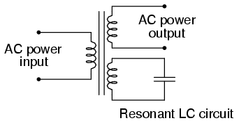
While being somewhat difficult to describe without going deep into electromagnetic theory, the ferroresonant transformer is a power transformer engineered to operate in a condition of persistent core saturation. That is, its iron core is "stuffed full" of magnetic lines of flux for a large portion of the AC cycle so that variations in supply voltage (primary winding current) have little effect on the core's magnetic flux density, which means the secondary winding outputs a nearly constant voltage despite significant variations in supply (primary winding) voltage. Normally, core saturation in a transformer results in distortion of the sinewave shape, and the ferroresonant transformer is no exception. To combat this side effect, ferroresonant transformers have an auxiliary secondary winding paralleled with one or more capacitors, forming a resonant circuit tuned to the power supply frequency. This "tank circuit" serves as a filter to reject harmonics created by the core saturation, and provides the added benefit of storing energy in the form of AC oscillations, which is available for sustaining output winding voltage for brief periods of input voltage loss (milliseconds' worth of time, but certainly better than nothing)


In addition to blocking harmonics created by the saturated core, this resonant circuit also "filters out" harmonic frequencies generated by nonlinear (switching) loads in the secondary winding circuit and any harmonics present in the source voltage, providing "clean" power to the load.


Ferroresonant transformers offer several features useful in AC power conditioning: constant output voltage given substantial variations in input voltage, harmonic filtering between the power source and the load, and the ability to "ride through" brief losses in power by keeping a reserve of energy in its resonant tank circuit. These transformers are also highly tolerant of excessive loading and transient (momentary) voltage surges. They are so tolerant, in fact, that some may be briefly paralleled with unsynchronized AC power sources, allowing a load to be switched from one source of power to another in a "make-before-break" fashion with no interruption of power on the secondary side!


Unfortunately, these devices have equally noteworthy disadvantages: they waste a lot of energy (due to hysteresis losses in the saturated core), generating significant heat in the process, and are intolerant of frequency variations, which means they don't work very well when powered by small engine-driven generators having poor speed regulation. Voltages produced in the resonant winding/capacitor circuit tend to be very high, necessitating expensive capacitors and presenting the service technician with very dangerous working voltages. Some applications, though, may prioritize the ferroresonant transformer's advantages over its disadvantages. Semiconductor circuits exist to "condition" AC power as an alternative to ferroresonant devices, but none can compete with this transformer in terms of sheer simplicity.


Well that about sums up the tranny for you. The switching freq of the diodes is very very low, so normal ones will be fine. Like I say, It seems that your ones are ok. I'd push the batt voltage to at least 14v per 12v batt with the lester and then look at the lower current small one for finishing charge... I think your batts are barely charged at less than 13v with the lester as the current is pretty high with these things, and pushes the apparent voltage quite high, while really without the charger on, the batts are no where near charged. I 'm guessing if you measure the plate charge 1 hour after disconnect at the present turn off time, your voltage will be quite low.... meaning probably nothing is draining the batts.... disconnect and see.

..

If you wish to decrease the output of the lester, change the cap to a smaller value (maybe 4uf) and your current will drop to a more reasonable 15A or so for your bulk charge. In this form you may well charge the batts to 14v/12v batt and then let it run at (guessing here 5A) for another hour to gass them mildly.


Anyway, I think at this stage the lester is fine, your problems may be your charging technique. Isolate the batts after charging them as you normally do and see if the low volt problem goes away, or remains the same. If the problem goes away, then look for a bleed from the truck somewhere else. If all else fails, disconnect the batts after charging till you find the problem, and get your milliamp meter back on line (is it internal fuse problem?)


best of luck


..........oztules

« Last Edit: August 29, 2007, 03:15:19 AM by oztules »
Flinders Island Australia

oztules

  • Hero Member
  • *****
  • Posts: 1477
  • Country: aq
  • Village idiot
Re: 36V Lester Matic Charger???
« Reply #7 on: August 29, 2007, 03:41:53 AM »
Afterthought....


Here is a small circuit I used when I played with these types of charger to make then automatic for traction packs when I used to convert this type from dial to auto


I may have a few boards left if you want one. It is a simple device to bulk charge until finish voltage is achieved (around 27.5v) and then times down for another 2 hours or so and turns off. It restarts when you interupt the supply to the logic circuits (unplugging the batteries) and restarts when you plug them back in. (or just have a momentry off switch in line with b+ to the board)


cheers


.........oztules

« Last Edit: August 29, 2007, 03:41:53 AM by oztules »
Flinders Island Australia

oztules

  • Hero Member
  • *****
  • Posts: 1477
  • Country: aq
  • Village idiot
Re: 36V Lester Matic Charger???
« Reply #8 on: August 29, 2007, 03:45:48 AM »
Curses..... that should read 41.3v for countdown sequence to begin for 36v system, (the 27.5 is for 24v version)


........sorry


.........oztules

« Last Edit: August 29, 2007, 03:45:48 AM by oztules »
Flinders Island Australia

FrankG

  • Full Member
  • ***
  • Posts: 121
Re: 36V Lester Matic Charger???
« Reply #9 on: September 03, 2007, 06:44:13 AM »
ElecTrac,


I've checked and double checked for any solenoid activity when connecting and disconnecting the B+ line from the pack, there is none, though I did notice that the foot throttle does tend to stick slightly at it's very top position (which engages the forward field Solenoid)...


It's entirely possible that it was the problem all along.


I just got in last night and have been trying to clear-up the back-log of emails and the like before I head back into the shop.


I just did a quick browse on what an Elec Trac looks like, a very nice machine was my conclusion...


...fg

« Last Edit: September 03, 2007, 06:44:13 AM by FrankG »

FrankG

  • Full Member
  • ***
  • Posts: 121
Re: 36V Lester Matic Charger???
« Reply #10 on: September 03, 2007, 06:59:11 AM »
Oz,


Thanks for the Ferro-Res info!!! I hope that you only cut & pasted...


What an ingenious idea.


As I just replied to Elec Trac, I think the initial problem may have been the sticky foot throttle that may have left the field coils energized...


As well I think you have hit on a good point on the batteries not being fully charger (Plate-Charged)... It was quite chaotic around here for the last 2 days before we left and will be for another day, but by Wed I should be back on track and will apply a long (8Hr) charge via the Lester-Matic... As well I will replace the dead meter (unfortunately it was not the fuse, as it read 10V, 10 ohms, or 10 Amps constantly, regardless of whether the leads were connected to a curcuit or not)...


Since it looks like the charger is working properly, I think that I'll leave it entact (for now) as I hope to add a second bank of the same batteries in a month...


Unfortunately the images of your controller didn't display on my end, is it PicAxe based or another ucontroller???


...fg

« Last Edit: September 03, 2007, 06:59:11 AM by FrankG »

oztules

  • Hero Member
  • *****
  • Posts: 1477
  • Country: aq
  • Village idiot
Re: 36V Lester Matic Charger???
« Reply #11 on: September 03, 2007, 09:58:19 PM »
Sorry Frank,


the images are pdf. (right click and open with your pdf viewer).

Cut and paste was the order of the day for the excerp on ferro trannies.


have fun with it


........oztules

« Last Edit: September 03, 2007, 09:58:19 PM by oztules »
Flinders Island Australia