Author Topic: 48 Volt windmill raised  (Read 7863 times)

0 Members and 1 Guest are viewing this topic.

DanB

  • Global Moderator
  • SuperHero Member
  • *****
  • Posts: 2151
  • Country: us
    • otherpower.com
48 Volt windmill raised
« on: August 18, 2004, 10:18:23 AM »


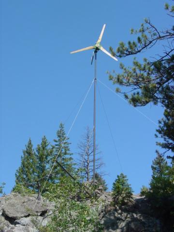
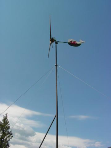
We had a busy weekend helping our freind and neighbor Adam get his 10' diameter, 48 volt wind turbine up.  We built this machine last fall, there are details about that HERE and some other discussion about its construction HERE.  The tail was to be a white whale... but he wound up painting the flag of wales on there...  he was born and raised there, it looks pretty neat.


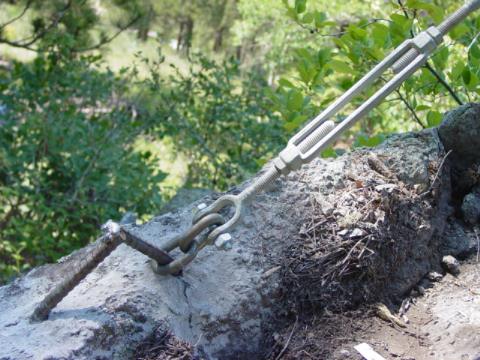
Pictured above is one of the guy wire mounts.  It's 2 pieces of 1/2" re-bar epoxied about 6" deep into the rock.  This whole tower is on rock - the base is mounted this way, all the guy wire mounts are about the same.  It was a tricky site - we had to carry lots of stuff (generator, welder, tools, pipe, wind turbine etc...) about 300' up a steep rocky hill.  The line is right at 300' long, the tower is just under 30' tall, up on top of a rock outcropping.


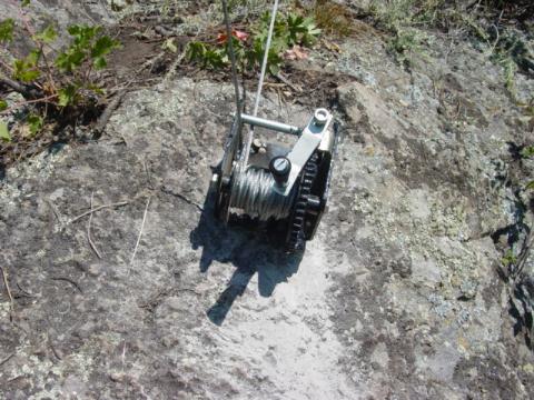
This tower is pulled up with an inexpensive hand cranked winch, which I welded to re-bar which is epoxied into the rock.  This little winch cost less than $20, its rated 2000 pounds (although I wouldnt trust that...  its a cheap winch!).  Its a wormgear winch... no ratchets to mess with.  While its very easy to crank - it takes LOTS of cranking to move this tower up and down.  It's handy that the shaft for the crank is 1/2" diameter.... we quickly discovered that removing the handle and chucking the shaft in a 1/2" variable speed drill makes things quite fast and easy.  This little tower goes up and down very nicely and seems quite safe.  The guy wires get just slightly loose on the way down and come up tight when it's raised.  It's very user freindly.


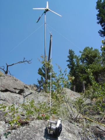
Here is a picture from below showing how the winch is attached to the jin pole.  The line through the tower is flexible 10 gage wire, which drops through the pipe and comes out a hole on the bottom.  The line from the machine, to the batteries is about 250' long.  We bring 3 phase down on 3 strands of 10 gage wire.  Again, it's a 48 volt system, so we can get by with 10 gage here.


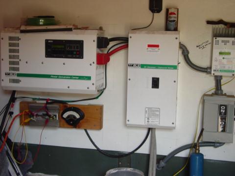
This is the wall in his power room.  Hes got a Trace SW inverter.  On the lower left you can see the board where we mounted bridge rectifiers and a meter for the windmill.  He's got about 400 watts of PV as well.  In a week or so, we'll get a dump load and rewire his Trace C40 as a diversion controller so he can use his PV and his wind turbine to help keep his battery room warm when his batteries are full.


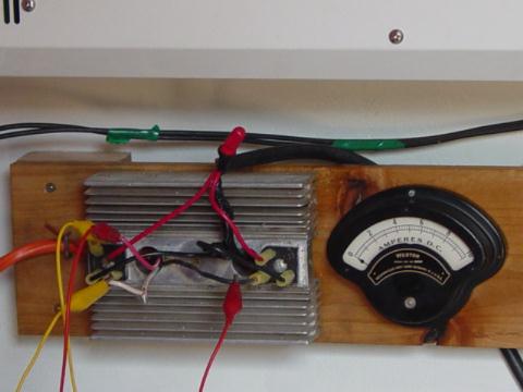
There's a closeup of his rectifiers and his meter.  We should have mounted the rectifiers in a vertical positions.. they'd cool better that way, but we decided that heat would probably not be too much of an issue with this machine at 48 volts.  I doubt well see much more than 15 amps here.  The meter only shows 10, which should be fine most of the time... I suspect there will be days when it'll be pegged.  (hope so!)  The messy jumper leads are attached there as a temporary shut down switch - so he can short it out easily if he needs to.  Soon we'll add a nice switch that does this a little more neatly and easily...


Another fun picture of it.  I've not seen any real wind at all on this one yet... it'll be interesting.  Odds are the blades will stall... most of the machines like this have had that problem.  We'll probalby wind up opening the airgap a touch and adding a bit of resistance to the line to get it right.   In the future Im using slightly smaller magnets on 10' machines I think.  We did see a bit of wind... about 2 amps on the meter on a very calm day (about 100 watts) - so it is working.  It's nice to finally get this one up!

« Last Edit: August 18, 2004, 10:18:23 AM by (unknown) »
If I ever figure out what's in the box then maybe I can think outside of it.

Flux

  • Super Hero Member Plus
  • *******
  • Posts: 6275
Re: 48 Volt windmill raised
« Reply #1 on: August 18, 2004, 10:45:32 AM »
Great job as usual, you make it all look so easy.


Ever tried reactors on the ac side of the bridge to reduce stall?  With wound field alternators with slots I always had too much leakage reactance, perhaps a little would help in higher winds.  Just thinking about that efficiency again.


Flux

« Last Edit: August 18, 2004, 10:45:32 AM by Flux »

DanB

  • Global Moderator
  • SuperHero Member
  • *****
  • Posts: 2151
  • Country: us
    • otherpower.com
Re: 48 Volt windmill raised
« Reply #2 on: August 18, 2004, 11:25:53 AM »
I never tried it...

Victor suggested it once - but I think we decided it would be of little use when were talking such low frequencies.  What do you think?  I suspect it tops out at about 40 hz (400 rpm).  Most of the time it'd be below 20 hz.  My understanding is that sort of thing works better at higher frequencies.

We could try to design alternators to work at higher frequencies (And then transformers might work better too) - but the problem is - especially with the dual rotor design, I think we need nice big magnets to overcome the airgap.  So a higher frequency alternator would need to be much larger, more expensive I think.  
« Last Edit: August 18, 2004, 11:25:53 AM by DanB »
If I ever figure out what's in the box then maybe I can think outside of it.

juiced

  • Full Member
  • ***
  • Posts: 243
Re: 48 Volt windmill raised
« Reply #3 on: August 18, 2004, 11:26:11 AM »
Thats truly inspriational.


  Can you give me a cost on the mill? I dont need to know about the controllers or anything.


  Im just curious why you build it last year and installed this year. I would have to assume the cost of controlling equipment.


  it looks like a rotor-style mill, am i correct?

« Last Edit: August 18, 2004, 11:26:11 AM by juiced »

whatsnext

  • Sr. Member
  • ****
  • Posts: 449
Re: 48 Volt windmill raised
« Reply #4 on: August 18, 2004, 11:59:20 AM »
Dan, I just looked over your excellent step by step genny building site. I was just thinking. Instead of trying to keep your two rotors square by tweeking the threaded rods with a pipe why not machine a collar that fits outside the threaded rods but inside the stator? This wouldn't be adjustable but you would be sure that everything would be nice and square.

John............
« Last Edit: August 18, 2004, 11:59:20 AM by whatsnext »

Flux

  • Super Hero Member Plus
  • *******
  • Posts: 6275
Re: 48 Volt windmill raised
« Reply #5 on: August 18, 2004, 12:17:20 PM »
The low frequency is a problem but I suspect that 1mH would have some effect on a 12 V alternator.

I don't think it is out of the question, some transformer cores with about 1/8" air gap and wound with some thick cable should prove the point.


I must try it , just wondered if anyone else had.


Flux

« Last Edit: August 18, 2004, 12:17:20 PM by Flux »

Gary D

  • Sr. Member
  • ****
  • Posts: 442
Re: 48 Volt windmill raised
« Reply #6 on: August 18, 2004, 01:59:59 PM »
Hi Dan, beautifull work! Wouldn't want to try that mount myself, too much lugging eguipment :-) Neat to see that the fourth guy wire can be downhill like that!

 I have yet to grasp the smaller wire bit though. I understand why you need the resistance, however I can't quite understand why the insullation doesn't melt with the high amps. The only comparison I can come up with is a heat tape....

It really doesn't matter if I understand it or not, just glad it works for you. More amps into the battery bank is a good thing! Keeping the tsr up is important as you've shown time and again. Thanks for sharing yet another mill! Gary D.
« Last Edit: August 18, 2004, 01:59:59 PM by Gary D »

Ungrounded Lightning Rod

  • SuperHero Member
  • ******
  • Posts: 2865
Re: 48 Volt windmill raised
« Reply #7 on: August 18, 2004, 06:33:52 PM »
We could try to design alternators to work at higher frequencies (And then transformers might work better too)


Transformers work FINE at low frequencies.  You just need to pick the right size transformer - one with a higher current rating than you'd use at a higher frequency.  (Transformers and generators are a marriage made in heaven.  The rules for core magnetization apply identically to both.)


The voltage and the frequency go up together as the mill speeds up, leaving the transformer peak magnetization unchanged.  (Which figures, since it's proportional to the magnetic field passing through the genny coils, which is constant on a magneto.)


It's even easier to see if the magneto is a motor conversion.  The current in the coils is the same for the transformer and the genny.  If you don't saturate the core of your transformer (or genny) at ONE speed, you won't saturate it at ANY speed.  (A transformer is just a half-motor and a half-genny back-to-back, with the half-motor simulating the magnet rotor for the half-genny's output coils.  B-)  )


Pick a speed (maybe faster than you'll ever run, extrapolating from performance at lower speeds) where the genny voltage matches the transformer voltage rating, then pick a transformer with a current rating that is adequate for the current the mill would produce at that speed.  Your transformer will be happy at any speed below that - or even above it, until the voltage gets high enough to arc it over.

« Last Edit: August 18, 2004, 06:33:52 PM by Ungrounded Lightning Rod »

Ungrounded Lightning Rod

  • SuperHero Member
  • ******
  • Posts: 2865
Re: 48 Volt windmill raised
« Reply #8 on: August 18, 2004, 06:44:14 PM »
I have yet to grasp the smaller wire bit though. I understand why you need the resistance, however I can't quite nderstand why the insullation doesn't melt with the high amps. The only comparison I can come up with is a heat tape....


It isn't that he needs the resistance.


It's that with a higher voltage he has a correspondingly lower current for a given amount of power.  So he can get away with thinner wire.

« Last Edit: August 18, 2004, 06:44:14 PM by Ungrounded Lightning Rod »

Nando

  • Hero Member
  • *****
  • Posts: 1058
Re: 48 Volt windmill raised
« Reply #9 on: August 18, 2004, 09:57:19 PM »
STALLING

I will repeat myself;

The wind mill industry still is trying to use the late 19 century and the early 20 century technology.


The wind mills generators ( DC) were designed to produce the battery bank voltage because the technology at that time did not have good materials, like huge selenium rectifiers with a lot of forward voltage losses.


So the generators produced the battery bank voltage for easy control.


With the present technology, it is best to produce a high voltage output, like 5 to 8 times the battery bank voltage and use a charge controller with MPPT to attain maximum power harvesting, also, be able to send the voltage long distance with low power loses.


We have systems that produce 240 to 480 volts AC at peak wind velocities and peak power capabilities that are converted at the battery bank, also all the wind mills have been Torque Pitch controlled with flat power output at high wind velocities, and some have the capability of semi-parking if the load was removed.


Regards


Nando

« Last Edit: August 18, 2004, 09:57:19 PM by Nando »

Victor

  • Jr. Member
  • **
  • Posts: 93
Re: 48 Volt windmill raised
« Reply #10 on: August 19, 2004, 04:31:48 AM »
Nando,


 You constantly say this


"With the present technology, it is best to produce a high voltage output, like 5 to 8 times the battery bank voltage and use a charge controller with MPPT to attain maximum power harvesting, also, be able to send the voltage long distance with low power loses."


 Surely by now you know that commercial  MPPT charge controllers for wind turbines are not available yet, I have a design for one that I want to build for MY machine when I get the time, but when I do it will only work for MY machine.


 It is useless for you to keep harping on this without any way for anyone to implement it. The people who have the knowlenge and abillity to build one on there own allready know the advantages. The commercial busnesses that are looking into it see the problems of the controller needing to be programmed or configured for each wind turbine design and will most likely never offer an off the shelf plug and play unit for any one to puchase and connect to their home built genny, and even if they do, until they do they havn't.


 I appoligize for the rant, but every time I hear you talk about this I feel like you are bateing people.


Victor


« Last Edit: August 19, 2004, 04:31:48 AM by Victor »

DanB

  • Global Moderator
  • SuperHero Member
  • *****
  • Posts: 2151
  • Country: us
    • otherpower.com
Re: 48 Volt windmill raised
« Reply #11 on: August 19, 2004, 06:42:44 AM »
Hi John-

yes, you could machine a spacer to do that - I've done that on some alternators with single rotors before.  I guess I normally don't, just because it's a bit more work... and the threads work pretty well.  I usually just put one nut under each stud on the front rotor now, and it's quite easy to get it running true by adjusting just 3 of them.. with a bent wrench that fits down inside the hole after the alternator is assembled. Once it sits nicely on 3 nuts, I bring the other two up to it.  It is nice to have it adjustable I think...
« Last Edit: August 19, 2004, 06:42:44 AM by DanB »
If I ever figure out what's in the box then maybe I can think outside of it.

DanB

  • Global Moderator
  • SuperHero Member
  • *****
  • Posts: 2151
  • Country: us
    • otherpower.com
Re: 48 Volt windmill raised
« Reply #12 on: August 19, 2004, 07:04:42 AM »
We put off raising it.. pretty much because Adam was too busy over the winter.  The site was daunting too... we wanted to procrastinate hauling all that stuff up as long as possible!  


The total cost... I figure probably about $400 - $500 for the machine, and perhaps the same for the tower and and everything else.  


Roughly...

Magnets: $250

Magnet wire: $50

Misc pipe/hardware: $25

Volvo strut, hub and rotors: $25

Resin: $15

Rectifiers and heat sink: $25

Wood for the prop: $60


Pipe for the tower: $100?? (I forget)

cable and turnbuckles for guy wires: $100

Winch: $20 (harbor freight special)

Wire down the tower and wire for the line: $100ish


I think thats most of it... I figure you could safely add another $100 for misc glue... broken drill bits, sand paper etc.


So perhaps $800 - $1000 for the whole deal here, that doesnt include batteries, or any sort of regulation.  In the future - I think the magnets for a 10' machine should cost less, smaller magnets would be appropriate.  Im builing one like it now that used the 1" X 2" X 1/2" blocks, I think they'll work better in most cases and that will knock about $100 off the price.  We are also in the process of updating a machine we put up last fall with a slightly longer tail, and a a slightly larger 11' prop.

« Last Edit: August 19, 2004, 07:04:42 AM by DanB »
If I ever figure out what's in the box then maybe I can think outside of it.

DanB

  • Global Moderator
  • SuperHero Member
  • *****
  • Posts: 2151
  • Country: us
    • otherpower.com
Re: 48 Volt windmill raised
« Reply #13 on: August 19, 2004, 07:22:22 AM »
Hi Nando..

yes, my take on that is with Victor..  my understanding is there is no such thing available yet - I know "they" are working on it, but the problem of MPPT and wind turbines is complicated.  and it will be expensive when it comes available I suspect, especially for low voltage battery systems that require the regulator to carry high currents.  My bet is that such a regulator, if it existed... could nearly double the price of a homebrew system like this.  I'm sure it's coming though - and when it does, (and when its affordable)- and when it's such that we can easily set it up for any system, then it will be quite handy...


and for me...

I'm quite fond of 19th and early 20th century technology!

« Last Edit: August 19, 2004, 07:22:22 AM by DanB »
If I ever figure out what's in the box then maybe I can think outside of it.

TomW

  • Super Hero Member Plus
  • *******
  • Posts: 5130
  • Country: us
Re: 48 Volt windmill raised
« Reply #14 on: August 19, 2004, 08:00:57 AM »
Victor;


AMEN.


T

« Last Edit: August 19, 2004, 08:00:57 AM by TomW »

Gary D

  • Sr. Member
  • ****
  • Posts: 442
Re: 48 Volt windmill raised
« Reply #15 on: August 19, 2004, 10:40:22 AM »
Not sure if this will raise some hackles or not (hope not), but windy boy has one for sale- grid tye for use with the African windpower 3.6... $2600. on the website below... Gary D.

http://www.npwr.com/african_wind_power.htm
« Last Edit: August 19, 2004, 10:40:22 AM by Gary D »

Gary D

  • Sr. Member
  • ****
  • Posts: 442
Re: 48 Volt windmill raised
« Reply #16 on: August 19, 2004, 10:43:53 AM »
Messed up the link, hope this works,sorry

http://www.nwpwr.com/african_wind_power.htm
« Last Edit: August 19, 2004, 10:43:53 AM by Gary D »

commanda

  • Hero Member
  • *****
  • Posts: 731
Re: 48 Volt windmill raised
« Reply #17 on: August 19, 2004, 03:15:44 PM »
Victor


Care to drop me an email, I'd like to discuss MPPT controllers with you. I'm also working on a design for one.


Amanda

« Last Edit: August 19, 2004, 03:15:44 PM by commanda »

Ungrounded Lightning Rod

  • SuperHero Member
  • ******
  • Posts: 2865
So what function must you use to implement MPPT?
« Reply #18 on: August 19, 2004, 04:35:56 PM »
With the present technology, it is best to produce a high voltage output, like 5 to 8 times the battery bank voltage and use a charge controller with MPPT to attain maximum power harvesting, also, be able to send the voltage long distance with low power loses.


It's a good idea.  But I have yet to see a description of what function you'd use to actually implement MPPT.


I assume if you put a down-converting switching regulator on the output of the mill and set it to the desired charging voltage and current limited it at the max of (max charging current going into batteries, max safe current for the regulator, max safe mill output), you'd put too much load on the mill and run it below the max power point (except when the current limit cut in and it ran above it instead, but it's OK then unless your dump load is useful).


So I suppose you'd want to modulate the current limit to let the mill come up to the max power point.


But what inputs do you use from the mill to do this, and how do you apply them?


Frequency?  Voltage?  Current?  Some function of voltage and current?


If you happen to KNOW how to do this, could you tell us please?


(MAYBE we could figure it out in several days of thought - and have a chance that we got it right rather than fooling ourselves.  But it would be much better to have someone who knows how this really works tell us than to try to reinvent this wheel.)

« Last Edit: August 19, 2004, 04:35:56 PM by Ungrounded Lightning Rod »

commanda

  • Hero Member
  • *****
  • Posts: 731
Re: So what function must you use to implement MPP
« Reply #19 on: August 19, 2004, 05:28:29 PM »
The design I'm working on has 3 analog inputs to the processor.


  1. : the rectified DC voltage from the alternator.
  2. : the battery voltage.
  3. : the current into the battery.


If 1: is below some preset minimum, do nothing. Blades aren't spinning fast enough so we take off all load.


If 2: is above some preset maximum, switch to float charge mode, and maybe turn on a diversion load (still working on this)


Otherwise, we're in bulk charge mode.

Increase the pwm slightly & see if the current into the battery increases, if it does, repeat.


If not, decrease the pwm slightly, and see if the current into the battery increases, if it does, repeat. Otherwise, go back to the previous step.


I'm sure there are some subleties to do with blades coming up to speed. I think it probably needs to be conservative in applying load when coming off step 1.


All comments welcome.


Amanda

« Last Edit: August 19, 2004, 05:28:29 PM by commanda »

Ungrounded Lightning Rod

  • SuperHero Member
  • ******
  • Posts: 2865
Re: So what function must you use to implement MPP
« Reply #20 on: August 20, 2004, 02:05:48 PM »
Increase the pwm slightly & see if the current into the battery increases, if it does, repeat.


If not, decrease the pwm slightly, and see if the current into the battery increases, if it does, repeat. Otherwise, go back to the previous step.


That will bring the blades to a screeching halt - or at least load them down far below the max power point.


You can always pull more power for a little while by increasing the load.  It takes the blades a while to slow down.  Your algorithm will see this and keep increasing the load, charging the battery momentarily with flywheel power from your mill while it keeps slowing down.


I think you're going to have to do something based on voltage and average current on the mill side (compensating for resistance to infer speed from voltage), with knowlege of the shape of the power curve to tell you which way the peak is relative to where you are.

« Last Edit: August 20, 2004, 02:05:48 PM by Ungrounded Lightning Rod »

commanda

  • Hero Member
  • *****
  • Posts: 731
Re: So what function must you use to implement MPP
« Reply #21 on: August 20, 2004, 04:48:54 PM »
I would have thought that as the blades started to slow, it would start reducing the load to keep the max power point.

I've also got am LM2917 tacho attached to it. Maybe I need to read the analog voltage from this as another input to the algorithm, so if it sees the blades slowing it knows to automatically step in the less pwm direction. Getting the algorithm balanced in changeable winds to maintain maximum power extraction will probably be more art than science.


Maybe it needs a lookup table of current versus rpm. Then hunt the pwm into the ballpark, then mppt from there.


We have a small wind tunnel at work (about 15 inches x 15 inches) which we use to calibrate hotwire anemometers we make for the coalmines. I might try & dig up a really small motor & hang some blades off it & do some testing.


Amanda

« Last Edit: August 20, 2004, 04:48:54 PM by commanda »

nack

  • Jr. Member
  • **
  • Posts: 65
Re: So what function must you use to implement MPP
« Reply #22 on: August 20, 2004, 09:21:55 PM »
I was going to suggest a tach.  If the alternator is somewhat characterized, you could use a lookup table.  Another idea might be to grab another input from an anemometer and with that + tach try to maintain TSR for optimum turbine performance, which might not present exactly the same load-lines as the genny alone.  


Another, somewhat more exotic idea is to take the AC in, and incorporate synchronous MOSFET rectifiers - has no bearing whatsoever on the MPP thing, but might reduce rectifier losses, which can be a noticable percentage in a low voltage system.  As a bonus side effect, you can count the zero crossings of any one phase to get your tach info.

« Last Edit: August 20, 2004, 09:21:55 PM by nack »

commanda

  • Hero Member
  • *****
  • Posts: 731
Re: So what function must you use to implement MPP
« Reply #23 on: August 20, 2004, 11:07:12 PM »
My Fisher & Paykel alternator makes about 50 volts per 100 rpm unloaded, so I'm not particularly concerned about rectifier losses, at least on the primary side.


Secondary side might be worth looking at a synchronous rectifier, especially as power levels go up. Pulling a tach signal from the synchronous rectifier on the secondary would only yield the chopper frequency of the switchmode.


Characterising the alternator is fairly simple. Volts/rpm unloaded, and internal impedance. If you know the open circuit volts, and voltage & current into a load, you can calculate the internal impedance. Maximum power transfer occurs when the load impedance is equal to the internal impedance. You can then calculate the ideal current to draw at each rpm, and the resultant voltage. This power then gives you a load current into your battery (assuming constant battery voltage). This assumes the blades are making more power at any given rpm than you're pulling out of the alternator.


The beauty of mppt, is that changes in blade speed with applied load is automatically taken care of. The system adjusts for maximum power from the system as a whole.


I truly hope this makes sense. At least I think I know what I meant to say.


Amanda

« Last Edit: August 20, 2004, 11:07:12 PM by commanda »

nack

  • Jr. Member
  • **
  • Posts: 65
Re: So what function must you use to implement MPP
« Reply #24 on: August 21, 2004, 07:01:03 AM »
I was not assuming that the blades make more power than is extracted from the alternator, rather I was thinking of the mills that make billions of amps at 15 volts and need an extra mile of air-gap just to let them turn.  In that context, I think tuning for the turbine's curve might be more useful than impedance matching the load.


If you want to use the cheapest possible microcontroller, you may want to avoid lookup tables, as they tend to eat memory.  Also, I may be grossly mistaken, but I don't think you need any more info on the alternator than expected volts/RPM (at load point).  If Z(source) = Z(load) the measured input voltage should equal measured RPM times volts/RPM to get in the ballpark.  Much less memory than lookup table, and simpler code to boot.

« Last Edit: August 21, 2004, 07:01:03 AM by nack »

commanda

  • Hero Member
  • *****
  • Posts: 731
Re: So what function must you use to implement MPP
« Reply #25 on: August 21, 2004, 04:44:18 PM »
Good point. Set 2 variables in the header; volts/rpm open circuit, and Z. With an input for rpm, the target current can be calculated. If the rpm is varying significantly, just track this. If the rpm is relatively stable, go with mppt.


I can see an intelligent system which, given a certain rpm, and having hunted the ideal mppt point, saves this value for future reference.


One of my failings in life, is I over-engineer everything to the n'th degree.


Amanda

« Last Edit: August 21, 2004, 04:44:18 PM by commanda »

Nando

  • Hero Member
  • *****
  • Posts: 1058
Re: 48 Volt windmill raised
« Reply #26 on: September 25, 2004, 01:15:27 PM »
Victor :


Is not useless is awaking people to look for the proper charge controller.

I am attaching a simple article of one charger with MPPT.


I have done MPPT to high power.


Some maybe very happy with old technology, GOOD for those -- some may need better technology --It is up to them to search for what they need.


The design works with any variable power source -- wind, Hydro, solar and even fuel cells if high impedance, because it is not a microprocessor "program" it is a synchronous phase detector system.


Victor please stop being the Judge and the Jury in this group.


« Last Edit: September 25, 2004, 01:15:27 PM by Nando »

Nando

  • Hero Member
  • *****
  • Posts: 1058
Re: 48 Volt windmill raised
« Reply #27 on: September 25, 2004, 03:16:32 PM »


The attachment did not ATTACH

Trying again


Nando

« Last Edit: September 25, 2004, 03:16:32 PM by Nando »