Another fun Monday yesterday! Following is just a ton of pictures w/captions about what we did yesterday. Organizing my pictures and writing up a caption or two right after we play helps me to make web pages at a later date.
If I recall we got this machine to this point last Monday (or was that Thursday?) Following will be a bit of detail about how we put these together.
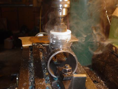
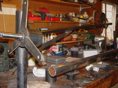
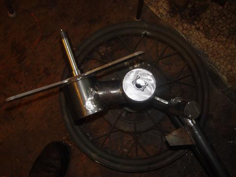
The Yaw bearing is made from a 12" long piece of 2.5" pipe. The alternator spindle is supported inside a 3" piece of pipe, which is held to the yaw bearing with a short 2" pipe. The 2" pipe is coped to fit around the yaw bearing for welding on one end, on the other end we simply cut a hole in the 3" pipe and it slips inside. This makes it easy to set the slight angle (About 4 deg) in the alternator so the blade tips will clear the tower. Pictured above I'm cutting the hole in the pipe that supports the alternator.
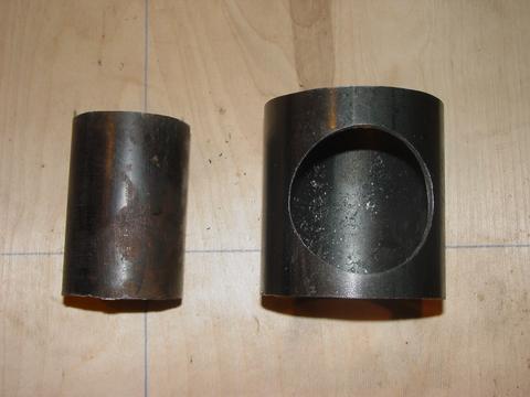
Above are the two pipes I was talking about before. The larger one will have the wheel spindle right through the center of it, supported on one end by a 3" OD and 1.25" ID 'washer' (cut from 1/4" steel), and on the other end by the stator bracket. The larger 3" dia pipe is cut 3 5/8" long, and the short pipe which attaches it to the yaw bearing is cut 3 1/2" long.
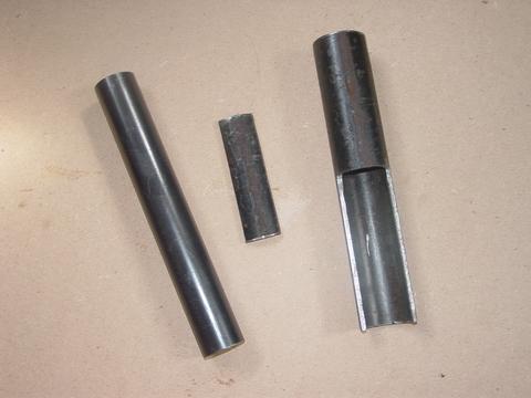
Pictured above are the pipes that will make up th tail pivot. The smaller one which is attached to the machine is 1" pipe, cut 9" long, the larger one will slip over that, and pivot with the tail. It's 1.25" pipe, also cut 9" long. The notch is pretty easy to cutout with a hacksaw or bandsaw... I used the milling machine. I cut almost half way into the pipe, and the cutout is 4 1/2" long. (actually this one was a bit shorter than 9" long, but most of them are 9" long and we notch out half of that)
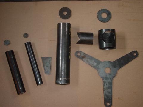
Here are most of the steel parts. Most of the flat ones I have cutout in town - it saves a lot of holesaw/torch abuse and they come out a bit nicer. All the pipe we cut here.
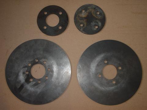
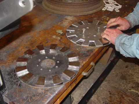
Here are the steel magnet rotors, and the 6" diameter 'blade hubs'. The blades will still be sandwiched between two 11" dia plywood hubs with bolts and lots of wood screws, but then we sandwich that between two steel plates. I find that if we just use washers to hold the blade on, they seem loose after a year or two because the wood crushes. Having nice large steel hubs to sandwich the blade between solves this I think. Notice one of the magnet rotors has 8 holes. 4 of them are tapped for jacking screws for lowering, and raising the front rotor. In the past I've used 2 jacking screws, that gets rather difficult. This makes things really easy and safe.
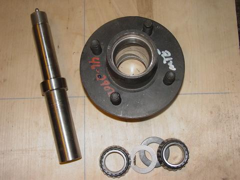
Here is the hub and spindle I'm using. It's a very 'generic' and common trailer hub setup. Its setup for 'easy lubrication' with a grease zirc in the front... Ill remove that. I dont think its a proper way to lubricate a bearing, and it also requires that we have the rear seal in there. The rear seal creates a good deal of drag and I prefer to remove it.
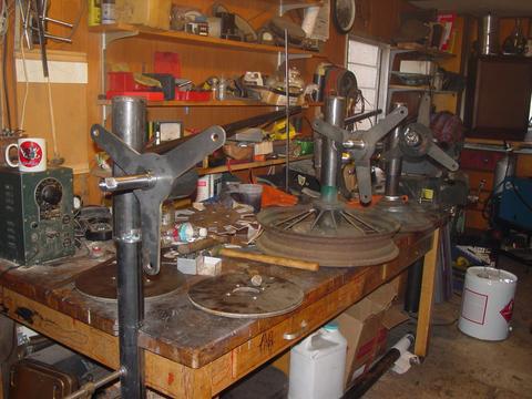
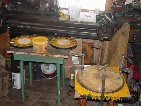
There are 3 almost identical machines with all their metal work finished up. As far as dual rotor machines from my trailer (shop) go... these ones are # 25, #26, and #27, and we stamp the parts so we don't get things confused. (they are not exactly identical)
Here George is putting down the magnets. I had a couple very nice Aluminum templates made up with a CNC machine, so they go down about perfectly. The template lines up with the 4 holes in center of the rotors.
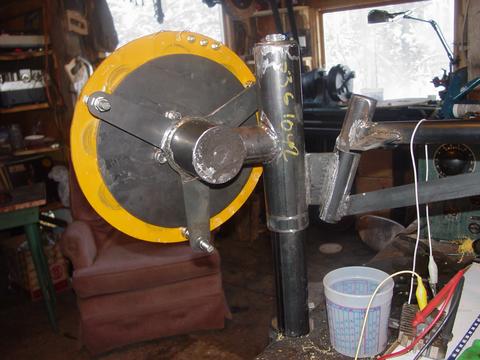
You can see the small 'stop' (made from 1/4" steel) thats welded to the tail. Rather than depending on the notch in the tail pivot to keep the tail out of the blades, I'm just welding this stop on now. I think it's stronger, and easier - it allows us less precision in milling (or cutting) out the notch in the tail bearing.
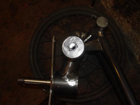
There is a picture of how the 'stop' will hit the yaw bearing in the fully furled position. Also notice the wire clamp, which is threaded into the yaw bearing cap. This will clamp the line that runs through the center of the tower.
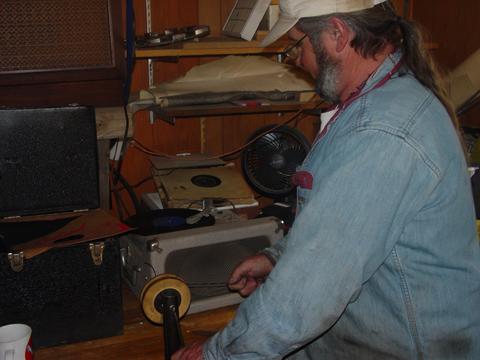
We wound coils for 2 stators yesterday. All day we listened to old 78's on the 'classic' Newcomb record playor (behind George). The goal was one coil per record (about 2 1/2 minutes).
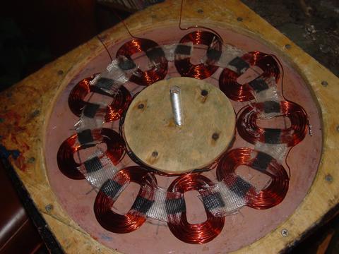
There the coils are all hooked up in Star, taped together and ready to be cast into the stator. This is a 48 Volt stator, the coils each have 125 windings of #16 wire. I expect this will cutin at around 130 rpm and we'll probably fit an 11' diameter prop to it. For smaller magnets, we'd wind this with 140 windings of #17 wire, for a cutin speed of 140 - 150, and we'd fit a 10' dia prop.
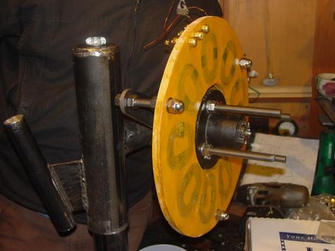
We decided on yellow for the resin this time...
Again (as usual) - after about 90 minutes the resin was hard, cooled down, and ready to remove from the mould. Im not sure why it goes so fast for me while other folks seem to have it take days. I mix it according to the instructions. Perhaps its the brand of resin I use? I've only once had an issue with it cracking in the mould, and that was on my larger 17' machine (almost a full gallon in the mould), and the cracks were minor. I've probably made between 25 - 30 of these so far, they all go off fast, and seem to come out fine.
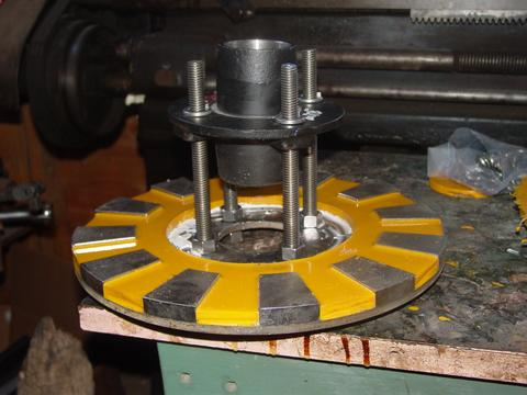
The back magnet rotor fits behind the wheel hub. There is one nut in between. When I use nuts for spacers - I use only high quality stainless nuts. I find they are all the same... where cheaper galvanized nuts are often not quite the same height. It's also nice for the long term to use all stainless hardware everywhere on the machine.
Usually before I assembled the machine I would paint it, but this time we decided otherwise. Here the back rotor is mounted.
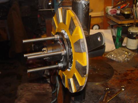
There we have the stator mounted. You can see how the hub fits right inside the stator. The hardware that holds the alternator together is like this...
The 4 studs are stainless, 1/2 - 13 allthread, cut 6 1/2" long.
Starting from the back of the machine...
The back rotor is held on by a nut, and a lock washer on each stud. There is one nut between the back rotor and the wheel hub. On the front side of the wheel hub we have another lock washer, and a nut. The front magnet rotor sits exactly on those 4 nuts, and that seems to give us a very nice safe, but reasonably close airgap. I feel fairly lucky on this - there is no need for any messing around or adjustments. I hope the thickness of all these 'Dexter' trailer hubs is the same... it makes life very easy.
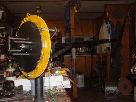
We got the alternator together last night around 7:00PM. There's a picture from the front.
Theres a picture from the rear. The cutin speed is right around 130 rpm as planned.
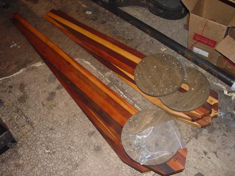
Scott brought up 2 new sets of blades. There is a 10' set for a future machine that fits this 4 bolt pattern, and another 11' 6"set that we'll be putting on Adams 48V machine (we built that over a year ago). Adams machine was built with the larger 2" dia X 1/2" thick disk magnets, and the cutin speed is too low for a 10' blade set - it also stalls badly. Scotts had the same problem, and he solved it by putting on an 11' 6" blade like this. Now it starts nicely and produces upwards of 2KW on windy days. We'll fix up Adams the same way. Click Here to see Scott and Adams wind turbines. (Scotts is the rooster, Adams is the whale!)
Lots of fun as usual... and and the end of it all Matt brought up pizza! (we kept going a couple hours after the pizza showed up)
Another fun thing about it all... with the exception of welding, everything in the shop is completely powered by wind and sun. Yesterday - it was all wind, we've not had much sun for a few days.
