Author Topic: Monday Oct 3  (Read 1655 times)

0 Members and 1 Guest are viewing this topic.

DanB

  • Global Moderator
  • SuperHero Member
  • *****
  • Posts: 2151
  • Country: us
    • otherpower.com
Monday Oct 3
« on: October 06, 2005, 06:25:07 PM »
Nothing too exciting last monday, but here's a bit of a diary about what we did.  We're finishing a wind turbine that'll be heading to Guemes Island (with us).  It's a slightly smaller (9' diameter) machine, but basicly everything else (other than the blades and a couple of windings in the coils) is about the same.


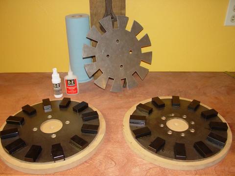
I believe epoxy coated magnets stand up a bit better to corrosion.  They also adhere better to the magnet rotors when using the cyanocrylate glue (super glue).  They cost slightly more, but I think it's an improvement.  So these are black, epoxy coated magnets 1" x 2" x 1/2" and we've glued them onto 12" diameter rotors.


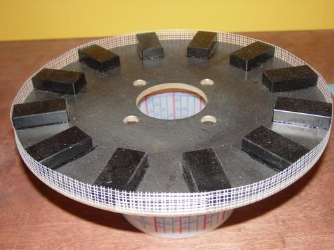
I've never had magnets fly out before, at least not since we've been using the furling tail system!  But I think this fiberglass drywall tape will add a bit to the safety factor.  I've run these rotors up to 800 rpm before with magnets on there which were not even glued on and they didn't move but it's always been a worry in the back of my mind.  This fiberglass tape is nifty 'cause it's sticky on one side.  It doesn't seem to stretch at all.  I ran around each rotor a couple of times with it.


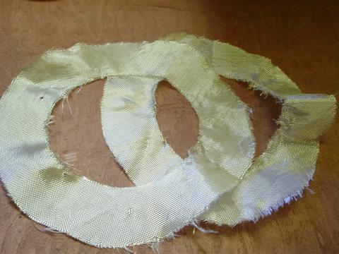
This time (and probably from now on) I'm totally encapsulating these magnets in resin.  It adds insurance that they will not corrode, or fly out.  So, we have the fiberglass tape around the outside of the magnets, and we'll put these fiberglass rings over the top - pretty much exactly as described in Hugh Piggott's plans.


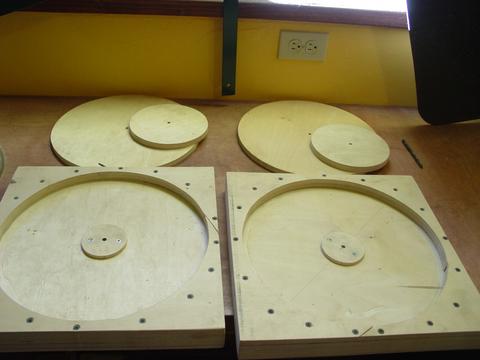
I made up two moulds to cast the magnet rotors in.  The disks go in first, then the 'islands' (7" diameter disks) go on top of those, then the lid.  It's all pinned to keep everything on center.


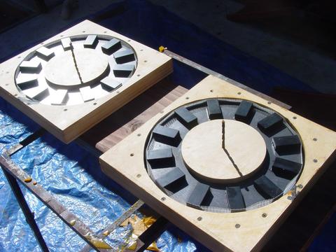
Here the magnet rotors are in their moulds ready for casting.


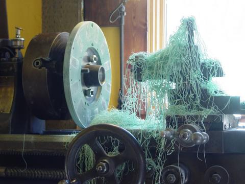
While there's nothing really wrong with them as they come out of the mould, I thought they'd look better and appear to turn more 'truely' if I turned them down in the lathe after they come out.  This really made them look pretty nice and it was easy/fast.  I'd made the moulds a bit oversized with this in mind.  The magnet rotors are 12" dia.  I made the mould 12.5" and turned them down to 12.25".


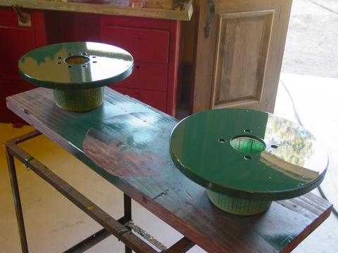
Once out of the lathe we primed, and painted the magnet rotors, again - with 'British Racing Green' acrylic enamel.


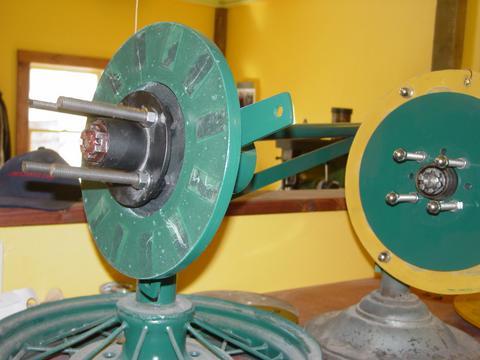
There's the new machine with one rotor on there.


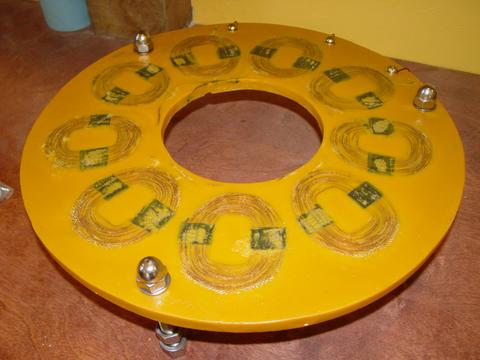
Here's the stator we made last week.  We only had to install the hardware on it this week.  We also took the time to fill some of the air bubbles with more yellow resin and sand it off - for appearance only.


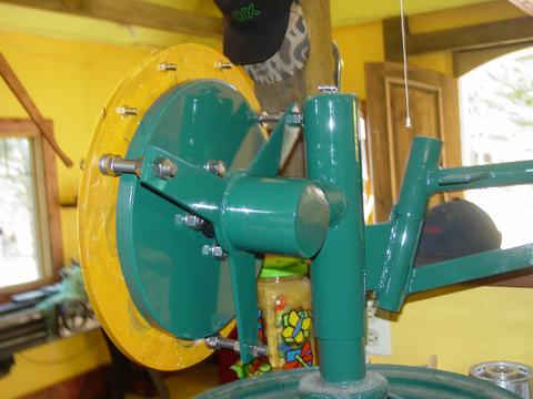
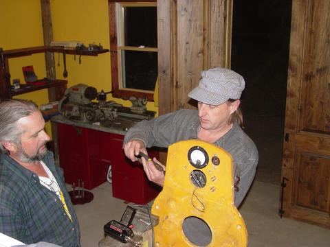
There's the back of the finished alternator after we got it all assembled.  The cutin speed may be a touch low for a 9' machine @ 150 rpm.  We'll try it first, if it needs adjustment we'll open the airgap a bit...  or fit a larger blade set.


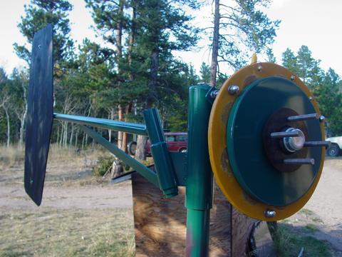
We put it outside on a stand and assembled it.


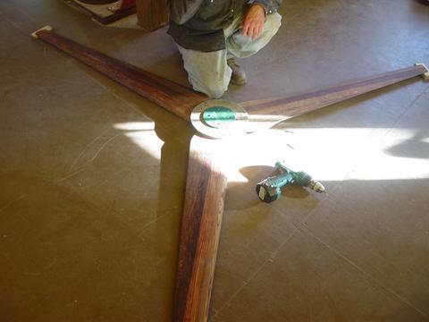
Scott made the blades for us.  We assembled them and drilled out the hub.  It's sure nice to have a flat space big enough to do this easily in the new shop.


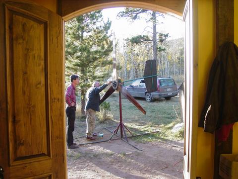
Here George is fitting the blades onto the finished machine.  Another one finished up!  This one is #32 of the dual rotor machines...


Later in the evening we had pizza as usual.  Scott pulled the stator out of the diesel generator we made so that he could button up some of the wiring a bit better.  That project is basicly done, we'll assemble it hopefully for the last time next Monday.

« Last Edit: October 06, 2005, 06:25:07 PM by (unknown) »
If I ever figure out what's in the box then maybe I can think outside of it.

steak2k1

  • Jr. Member
  • **
  • Posts: 75
Re: Monday Oct 3
« Reply #1 on: October 06, 2005, 05:06:59 PM »
cpl of Questions for ya Dan.


What did you use to make the resin yellow.?  pretty neat color.


How much resin was on the face above the mags after the pour.?  I noted that you turned the diameter down from 12.5" diam to 12.25. So did you machine the front face area as well.?


I have used that drywall tape on many an occaision for it's intended use...works well...now that I have seen what you have done..found another.! (with me muttering / smiling "why the hey didn't I think of that.!")


Nice looking set for sure and I wouldn't hesitate to say, that they will stand up very well in any inclement weather.


rgds,


stk

« Last Edit: October 06, 2005, 05:06:59 PM by steak2k1 »

DanB

  • Global Moderator
  • SuperHero Member
  • *****
  • Posts: 2151
  • Country: us
    • otherpower.com
Re: Monday Oct 3
« Reply #2 on: October 06, 2005, 06:14:14 PM »
"What did you use to make the resin yellow.?  pretty neat color."


Just a bit of acrylic enamel in the resin.  It seems to also make it less brittle.  


"How much resin was on the face above the mags after the pour.?"


The lid of the mould smashes right down to the face of the magnets.  So only the thickness of 1 layer of 'smashed' fiberglass fabric.  I expect it's less than 1/32".


"So did you machine the front face area as well.?"


No, just the sides.  One side of the rotor is bare steel, the other is the magnets.

« Last Edit: October 06, 2005, 06:14:14 PM by DanB »
If I ever figure out what's in the box then maybe I can think outside of it.

nothing to lose

  • Hero Member
  • *****
  • Posts: 1538
Re: Monday Oct 3
« Reply #3 on: October 06, 2005, 06:19:07 PM »
Excellent job as always.

I like the way you turned them down after casting the mags in resin. I think for an area with ice problems that should help stop ice buildups also inside the genny.
« Last Edit: October 06, 2005, 06:19:07 PM by nothing to lose »

hiker

  • Hero Member
  • *****
  • Posts: 1661
  • BIG DOG
Re: Monday Oct 3
« Reply #4 on: October 06, 2005, 07:41:41 PM »
looks great dan...

as far as mags flying off--what works great is nylon tape--just wrap a few turns around the mags..works great-i just use super glue and tape...even when my old 12"sawblade mill came apart--the mags still stayed in place after chewin up the stator.....
« Last Edit: October 06, 2005, 07:41:41 PM by hiker »
WILD in ALASKA

kudu

  • Newbie
  • *
  • Posts: 10
Re: Monday Oct 3
« Reply #5 on: October 06, 2005, 09:25:06 PM »
A very slick, tidy setup, Dan.  I know you're proud of it.

Another HAWT out the door!

Just wait til you see my Racing Green VAWT, you'll be drooling.

Kudu
« Last Edit: October 06, 2005, 09:25:06 PM by kudu »

Shadow

  • Sr. Member
  • ****
  • Posts: 473
Re: Monday Oct 3
« Reply #6 on: October 06, 2005, 09:32:52 PM »
Very professional looking work!By totally encasing the magnets in resin now,I presume you dont see heating as an issue? I know some of your early rotors you left a portion of the magnets protruding, to 'disturb' some air. I like this idea of totally covered as it may also deter snow and ice buildup way up north here.Great to have 'Mondays,by DanB' back again!
« Last Edit: October 06, 2005, 09:32:52 PM by Shadow »

RP

  • Hero Member
  • *****
  • Posts: 722
  • A dog with novelty teeth. What could go wrong?
Re: Monday Oct 3
« Reply #7 on: October 06, 2005, 10:28:37 PM »
I'm curious about increasing the airgap for a higher cut in speed.  

Is this the same as having weaker magnets?  Also, could this also be addressed electronically with a speed sensitive cut-in switch circuit or simply adding a few diodes in line to add a little fixed voltage drop before the batteries?
« Last Edit: October 06, 2005, 10:28:37 PM by RP »

Flux

  • Super Hero Member Plus
  • *******
  • Posts: 6275
Re: Monday Oct 3
« Reply #8 on: October 07, 2005, 02:12:02 AM »
Yes, smaller magnets would have the same effect (less flux)


Don't get too hung up on the cut in speed, that is not the issue. If the alternator makes too much power at too low a speed the prop will stall and fall off the peak of its power curve. The issue doesn't show at cut in, it makes itself obvious in winds around 12 to 15 mph typically and you reach a point where output fails to rise above this.


This is the region where you want to raise the alternator speed to clear the stall.


If you have got things about right, you can move the cut in speed a bit either way without significant loss as the prop is running fast at this point and will adapt its speed to accept the load. Obviously you can't be miles out, but this air gap change is only for fine tuning to keep prop just above stall.


The switching circuit won't help as the stall problem is not directly at cut in.


The diode method would probably clear the stall if you added enough but would add significant losses and raise cut in speed to an undesirable extent.


What you really want to do is add more slope to the alternator speed curve so that it is nearer parallel to the prop power curve.


I produced this graph for another reason but it does very well show the effects of stall. It is for a 6 ft machine with a very powerful alternator that stalls badly and you will see that at cut in it is working ok and the effects start to take effect at higher speed as the prop tsr comes down to a critical speed.


The second ( middle curve) is with added resistance and has much the same effect as a moderate increase in air gap ( except that it doesn't affect cut in speed but adds losses)


Not relevant here but the top curve shows the effect of electronic tracking to keep the prop tsr optimum over the speed range.


Flux

« Last Edit: October 07, 2005, 02:12:02 AM by Flux »

RP

  • Hero Member
  • *****
  • Posts: 722
  • A dog with novelty teeth. What could go wrong?
Re: Monday Oct 3
« Reply #9 on: October 08, 2005, 09:01:00 PM »
Thank Flux.  That helps a lot.  I always the problem was a cut-in rather than higher up the power curve.
« Last Edit: October 08, 2005, 09:01:00 PM by RP »

canadianfred

  • Newbie
  • *
  • Posts: 10
Re: Monday Oct 3
« Reply #10 on: October 18, 2005, 05:50:53 AM »
Hi Dan.


Now that you have a working system for producing windmills, how long does it take, once you have all the materials at hand, to make one of your windmills?


Do you have volts-amps-watts/windspeed data for your various windmills, for example the 10' diameter models that you usually make?


Why 9' for this windmill, instead of the usual 10'? Easier to transport the blades?


How thick are your magnet rotors?


Your laser cut parts sure look smooth and professional. I phoned a few places in the yellow pages in my area to find someone to do that for me, and the few places that I called are busy enough to turn down small jobs.


    Thanks,

    Fred

« Last Edit: October 18, 2005, 05:50:53 AM by canadianfred »

DanB

  • Global Moderator
  • SuperHero Member
  • *****
  • Posts: 2151
  • Country: us
    • otherpower.com
Re: Monday Oct 3
« Reply #11 on: October 19, 2005, 09:29:27 AM »
Hi Fred -


"Now that you have a working system for producing windmills, how long does it take, once you have all the materials at hand, to make one of your windmills?"


I expect about 20 hours, not counting the blades which Scott makes.


"Do you have volts-amps-watts/windspeed data for your various windmills, for example the 10' diameter models that you usually make?"


It's very similar to older 10' machines, but I do not have very scientific ways to test things.  I need to work on that.  I think I get a pretty good intuitive idea though about whats working well, and what's not from watching quite a few machines up here and making adjustments.  


"Why 9' for this windmill, instead of the usual 10'? Easier to transport the blades?"


Only because they requested a 9' machine, I think they were nervous about putting a 10' machine on their tower.


"How thick are your magnet rotors?"


1/4"


"Your laser cut parts sure look smooth and professional. I phoned a few places in the yellow pages in my area to find someone to do that for me, and the few places that I called are busy enough to turn down small jobs."


They're actually water jet cut, laser cutting would probably be cheaper.  I get folks asking if I'd sell rotors - at this time I prefer not to, because out of one sheet of steel I get exactly the parts for 8 wind turbines.  If I sell rotors, then I wind up with 'extra parts' that I cannot use.  If you're looking to buy rotors, I'd maybe ask Ed at windstuffnow.com, I think he still sells 12" rotors.  Much cheaper to have it done locally though if you can.


    Thanks,

« Last Edit: October 19, 2005, 09:29:27 AM by DanB »
If I ever figure out what's in the box then maybe I can think outside of it.

willib

  • SuperHero Member
  • ******
  • Posts: 2414
  • Country: us
Re: Monday Oct 3
« Reply #12 on: November 19, 2005, 11:47:42 PM »
interesting top curve Flux , is that a buck converter? , what frequency is it running at?

i have often thought that a wind generator would be best , when hooked to an RPM gage , so that when it started to slow down you could take a little load off and when it was speeding up you could add a little more load to it..

nice graph btw..
« Last Edit: November 19, 2005, 11:47:42 PM by willib »
Carpe Ventum (Seize the Wind)