Author Topic: Monday Feb 6  (Read 4357 times)

0 Members and 1 Guest are viewing this topic.

DanB

  • Global Moderator
  • SuperHero Member
  • *****
  • Posts: 2151
  • Country: us
    • otherpower.com
Monday Feb 6
« on: February 07, 2006, 05:45:38 AM »


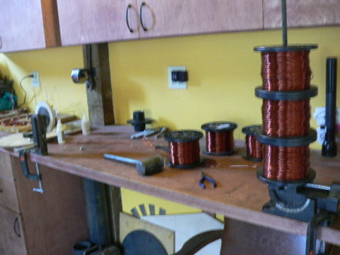
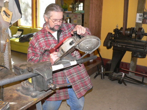
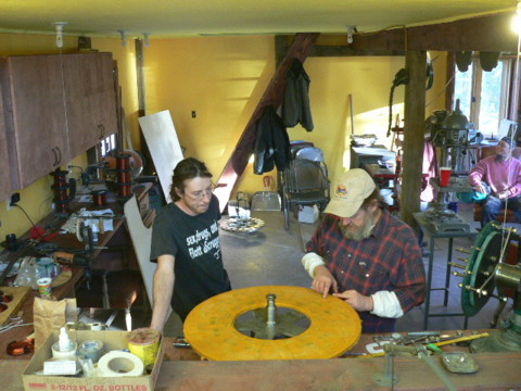
Last Thurs I made a posting about testing the a coil for this machine.  The plan is a 20' dia wind turbine and I figured that I needed 45 windings, which I could barely fit with 3 strands of #15 gage wire.  Pictured above are three spools of #15 gage wire and the coil winder in the back ground.


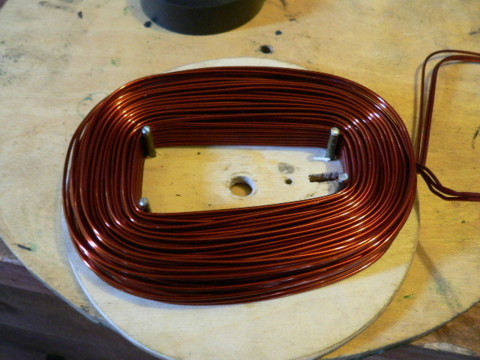
I used the same coil winder I made last year (actually late 2004) for my 17' machine, but I drilled out 4 holes and inserted pins to make the hole in the middle larger.  Pictured above is one of the coils for the new machine on the coil winder.  The pins on this insert through the front of the coil winder so the coil comes off with the front of the coil winder.  Once I take that off I press the coil flat with a dowell and soak super glue into it.  The I turn it upside down (the coil falls off) and I put more super glue into the back of it.  Then we tape up the legs with some electrical tape.


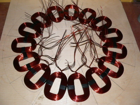
The mold is not finished yet, but the bottom is layed out and the positions in which the coils must lay is marked on what will be the bottom of the mold.  These fit about perfectly I think.  Again, we have 22" dia magnet rotors, with 20 1.5" x 3" x .75" thick magnets on each one.  The overall diameter of the stator is 28" in diameter.


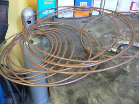
I used this old copper tubing (1/4" I think) that was previously used as the primary coil on an old tesla coil I made as connectors between the coils.  It's handy to poke the wires in, crimp them - and solder them.


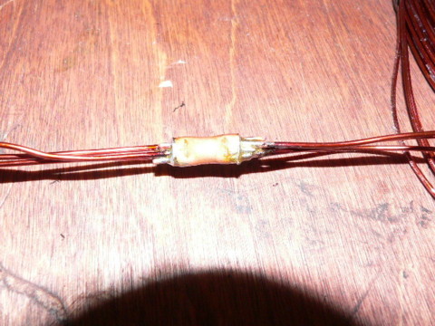
Theres an example.  The tubing fits 6 strands (3 from each coil) very nicely and the connections came out very nice.  We did something like this last week on Scotts wind turbine but with fewer strands and smaller tubing.


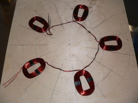
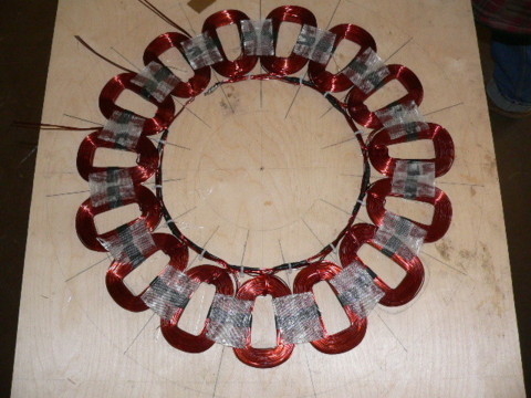
Theres one phase all wired up and sitting on what will be the bottom of the mold.


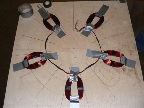
Then we get each coil postioned exactly where it should be, and taped down..  Pictured above is one phase in its postion.


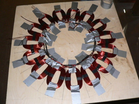
There we have all three phases taped down into postion.


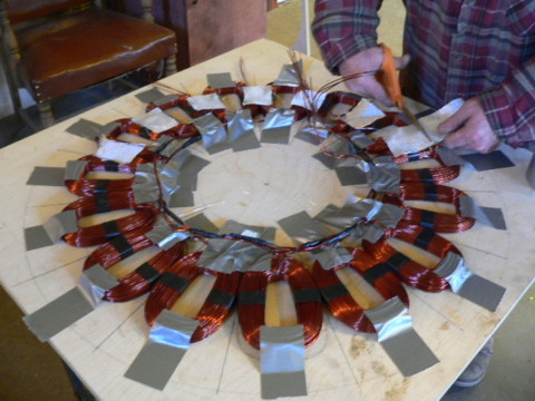
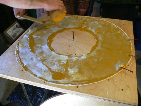
George is cutting out 2" x 2" squares of fiberglass cloth and placing them between the coils.  We'll soon glue those there to hold the coils in place so the stay that way before we cast them.  (we have to move them around inbetween now and then)


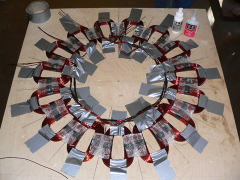
Then we use cyanocrylate glue (superglue) to stick the fiberglass cloth to the coils (we also run lots of it into the cloth inbetween the coils) to make it fairly rigid so we can move the stator around without changing the position of coils or anything.


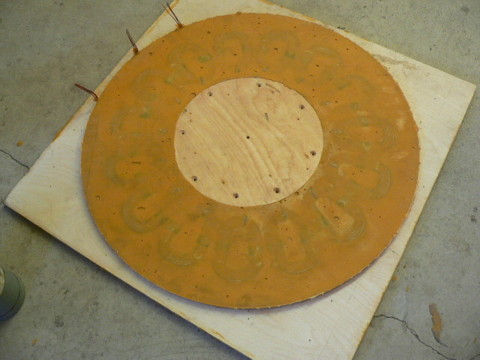
We've removed the duct tape - all the fiberglass is glued down.  We've also used 'zip ties' to hold all the wiring together on the inner diameter.  At about 11:00 you can see where we made the star connection between the three phases.


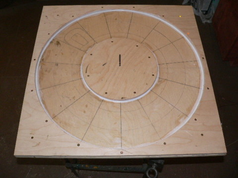
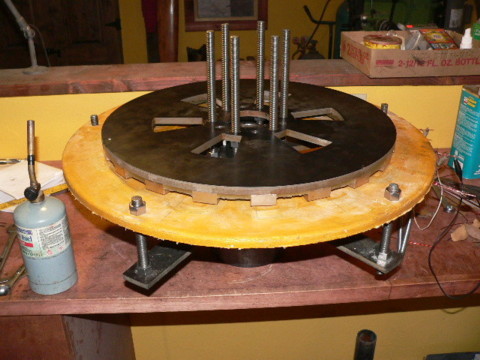
Pictured above the mold is finished.  The OD is 28", the island in the middle is 12.5" in diameter.  We used caulk around all the edges to smooth things out and make sure no resin can run under the wood.  The mold is screwed together with wood screws - we countersunk them all so everything is nice and flush.


In the mean time - George cut out tail pivots, tail bearings, and yaw bearings for 5 more small (10' diameter) machines.


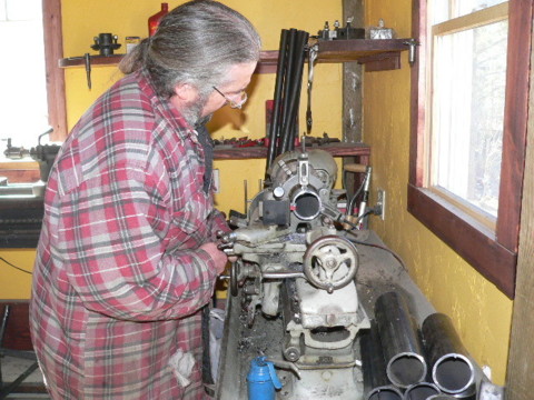
After we cut bits of pipe for windmills we usually face them off in the lathe to the right length, and get make sure things are nice and square.


Its always tense for me (stressful)casting stators, especially one this big so lots of pictures did not get taken.  Here were at the end of it all just getting ready to put the lid on.  This took almost a gallon and a half of polyester resin.  We have a thick layer of fiberglass matt on one side, two layers of fiberglass cloth on the other, and lots of fiberglass strips around the outside of it (inside) to give it extra strength hopefully.  Everything Ive casted thats 'big' in the past has cracked some - I wanted to give this all the strength I could.  We also mixed about half the hardener we normally do because of the volume here.


After two hours it had set up mostly and we pulled the lid off the mold.  It looked nice, a couple of very small (barely noticable) cracks, but nothing like on other large castings we've done.  Once the lid was pulled I let it cool and then tried to remove it from the mold.  It did not come easily -  I actually had to take all the screws out of the mold and pry things apart to remove the stator.  I've never had so much trouble.  Maybe just due to the surface area - hard to say.  We used 'Crisco' for mold release this time (its worked well in the past) - maybe I should look into something else.  The stator wound up cracking (some bits stuck to the mold and broke out of hte stator) - but not too bad, better than Id hoped for.


Tom and I discuss the cracks in the stator...

we decide it's no big deal, we'll drill it out, assemble it, and epoxy up the cracks later.


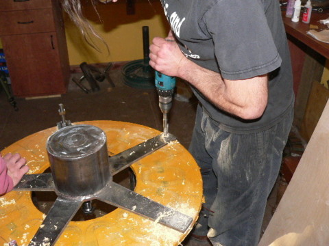
I put the stator down on a stand and put the frame of the alternator over it (spindle poking down through the stator) and drill through the stator with a 5/8" bit for the studs that will mount it to the alternator.


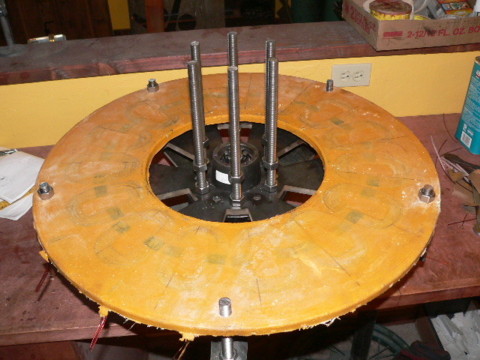
Then we mounted the bottom magnet rotor to the alternator frame, and mount the stator over it.


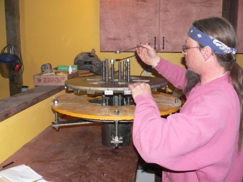
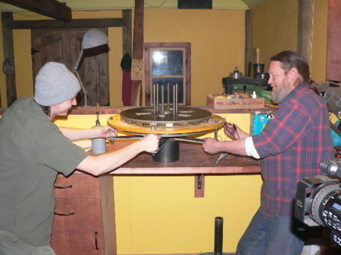
Adam helps to patienly lower the top rotor down with 3 jacking screws.  This process takes about an hour.  If it gets crooked, it either binds up, or tips over...  trick is, 1/2 turn per screw, one screw at a time... lots of patience.


There it is finished (mostly) - we just need to test it (volts/rpm).  Then well take it all apart again,finish the metal work, paint it etc..  


Adam and Tom are amused with it.  It is quite amazing how rapidly this stops (its downright violent) if you spin it up and short it out.  It's incredibly stiff to turn when shorted out.  Past that...  we've not tested it tonight but it seems quite impressive.


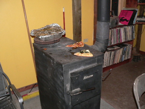
Matt and Daphne brought up pizza as usual.  If its not hot enough when it gets here... you can always put it on the riteway for a bit and it's better than new!

Also notice the aluminum container which contains 'buffalo ribs' that George brough up (luch!).


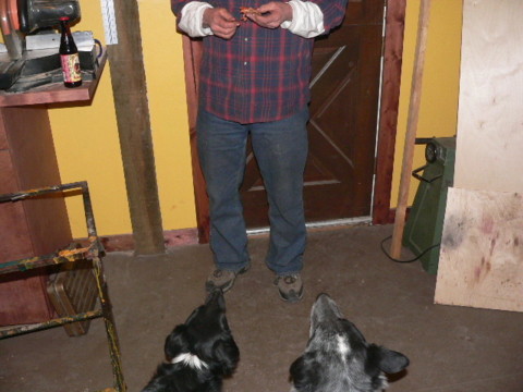
and of course dawgs begged...


One other note about my 17' machine since we fixed it last week (we opened the airgap a bit).  Yesterday is was very windy and I saw a 'record' 96 amps from it (I only watched for 10 min so it probably did more) and it was pushing my fairly low batteries up to 64 Volts (not good) because the heaters could not dump enough power.  I shut it down... but it is interesting how much better it works in high winds now (too well - probably in stator melting zone if Im not careful) that Ive opened the airgap up and extra .1".  Its still fine in low winds, but much too powerful in high winds, it needs to be closed up and the blades really need to stall a bit more in high winds I think.

« Last Edit: February 07, 2006, 05:45:38 AM by (unknown) »
If I ever figure out what's in the box then maybe I can think outside of it.

willib

  • SuperHero Member
  • ******
  • Posts: 2414
  • Country: us
Re: Monday Feb 6
« Reply #1 on: February 06, 2006, 11:13:30 PM »
Its sad that the hole in your stator 12.5" is larger than the rotors on my testbed.

sad for me! not you ..

its amazing how large that is when there is somone in the picture for perspective..

 do you think there is too much distance between the stator mounts? just a thought .
« Last Edit: February 06, 2006, 11:13:30 PM by willib »
Carpe Ventum (Seize the Wind)

DanB

  • Global Moderator
  • SuperHero Member
  • *****
  • Posts: 2151
  • Country: us
    • otherpower.com
Re: Monday Feb 6
« Reply #2 on: February 06, 2006, 11:19:43 PM »
"its amazing how large that is when there is somone in the picture for perspective..

 do you think there is too much distance between the stator mounts? just a thought ."


I hope not -I've thought about that.  The stator bracket is very rigid (3/8" steel) and  the stator is thick (5/8") and were using 5/8" threaded rod.  I'm actually more worried about the distance between the bracket, and the stator - there is a lot of torque on the stator under load.  I could improve this... my inclination is to let it go till it becomes a problem though.  It may never be an issue - hard to say.  It is one of the first weaknesses that comes to mind though.

« Last Edit: February 06, 2006, 11:19:43 PM by DanB »
If I ever figure out what's in the box then maybe I can think outside of it.

willib

  • SuperHero Member
  • ******
  • Posts: 2414
  • Country: us
Re: Monday Feb 6
« Reply #3 on: February 06, 2006, 11:59:43 PM »
Thats about 15 inches, between stator mounting holes ?

potato chip , just kidding , but seriously you have to take it back apart anyway...
« Last Edit: February 06, 2006, 11:59:43 PM by willib »
Carpe Ventum (Seize the Wind)

DanB

  • Global Moderator
  • SuperHero Member
  • *****
  • Posts: 2151
  • Country: us
    • otherpower.com
Re: Monday Feb 6
« Reply #4 on: February 07, 2006, 12:05:09 AM »
the stator is very rigid, Im not so worried about 15" between mounting points.  Im more worried about the 4" or so between the stator brackets, and the stator itself.  I expect it will be OK though - time will tell!
« Last Edit: February 07, 2006, 12:05:09 AM by DanB »
If I ever figure out what's in the box then maybe I can think outside of it.

hiker

  • Hero Member
  • *****
  • Posts: 1661
  • BIG DOG
Re: Monday Feb 6
« Reply #5 on: February 07, 2006, 02:07:49 AM »
i allways put my coils in a vise-between two boards -then tork down with a extra bar on the handle--makes for some nice flat compact coils..............
« Last Edit: February 07, 2006, 02:07:49 AM by hiker »
WILD in ALASKA

nothing to lose

  • Hero Member
  • *****
  • Posts: 1538
Re: Monday Feb 6
« Reply #6 on: February 07, 2006, 03:16:04 AM »
"I'm more worried about the 4" or so between the stator brackets, and the stator itself."


That is kinda what I am wondering about. You said it wants to stop almost violiently when shorted, spun by hand. Is that any thing to worry about if you have to shut it down in high winds with those big rotors and 20' blades acting like a flywheel?

 You can see it in person, I wish I could!


Great work and post as normal. Gee YOUR Mondays are the highlight of MY life. :)


So I geuss next Mondays post will be testing this monster? I have to go to Ohio, geuss I'll have to take a computer with me and find an ISP when I get there. I can't miss that.


Hard to beleave your 17' was making TOO MUCH power. What will you do with all the power from this one?


And parts for 5 more 10' mills? Are these going to be sold?

« Last Edit: February 07, 2006, 03:16:04 AM by nothing to lose »

Frank06

  • Newbie
  • *
  • Posts: 24
Re: Monday Feb 6
« Reply #7 on: February 07, 2006, 04:33:58 AM »
Thanks again for posting these neat "Monday" items.  I hope this new machine works out okay.


In that photo of the lathe it looks like it's driven by some type of central "line shaft"? (belt descending magically from out of the photo)- just curious...

« Last Edit: February 07, 2006, 04:33:58 AM by Frank06 »

wind4Reg

  • Full Member
  • ***
  • Posts: 127
Re: Monday Feb 6
« Reply #8 on: February 07, 2006, 05:18:28 AM »
Great post, it is always nice to see lots of pictures and explainations. Can't wait to see the pics of the final unit.

wind4Reg
« Last Edit: February 07, 2006, 05:18:28 AM by wind4Reg »

FrankG

  • Full Member
  • ***
  • Posts: 121
Re: Monday Feb 6
« Reply #9 on: February 07, 2006, 05:29:27 AM »
Dan,


Like so many others, Tuesday is "The Day" to read up on Monday's progress. I certainly appreciate the additional work it must take to stop your work flow to snap photos at the appropriate stages through the project, and the write-up at the end of the day...


What do you add to the resin to get the various colours? I thought that I read somewhere earlier on that it was a mix of Talcum powder & ???. I tried Talc on the first batch of resin I mixed with no pigment... The result was a cloudy casting that was full of cracks. Not having a point of reference I've been hesitant to use the talc since, but it is a cheap filler considering Resin is considerably more expensive.

« Last Edit: February 07, 2006, 05:29:27 AM by FrankG »

Gary D

  • Sr. Member
  • ****
  • Posts: 442
Re: Monday Feb 6
« Reply #10 on: February 07, 2006, 07:58:26 AM »
Wow Dan if my calculator is correct, that's a 6.144kw peak! With your newer machine things will even get more exiting quicker! Have you thought out how you will control things yet? I'd bet that you are mulling things over! Bigger/duel 48 volt banks? An extra C60 or inverter to help dump the power? Perhaps a 50 or 80 gallon preheat hotwater tank to help cut down on Lp use? Lots to think of (and expense) on top of just upgrading your tower and rectifiers... Your posts are indeed great for "what if" thoughts!    Gary D.
« Last Edit: February 07, 2006, 07:58:26 AM by Gary D »

RobD

  • Full Member
  • ***
  • Posts: 116
Re: Monday Feb 6
« Reply #11 on: February 07, 2006, 08:31:14 AM »
Nice job Dan,

One thing I think I would put heat shrink tubing over the nails in your coil form. I get nervous about removing and winding coils in metal to metal contact.


RobD

« Last Edit: February 07, 2006, 08:31:14 AM by RobD »

nothing to lose

  • Hero Member
  • *****
  • Posts: 1538
Re: Monday Feb 6
« Reply #12 on: February 07, 2006, 10:24:19 AM »
Dan could tell you alot better than me what he does of course,


But in general the more hardener you mix into the resin the hotter it may get as it cures. Also it may change how fast it cures too. More heat and a faster cure is more likely to create cracks. Less hardener and it will cure at a slower rate with less heat and be less likely to crack.

 I geuss talc (baby powder) would give the resin a cloudy look at times. How dan gets the color I don't know really, but you can get a pigment to add to the resin in many different colors.

 When I do a daul rotor I think I will cast my stator in blue or red.


How much Talc you use could also have an effect on how much it cracks or how cloudy it gets perhaps.

« Last Edit: February 07, 2006, 10:24:19 AM by nothing to lose »

theTinker

  • Full Member
  • ***
  • Posts: 104
Re: Monday Feb 6
« Reply #13 on: February 07, 2006, 11:34:21 AM »
i have the same fear, i never thought of heat shrink :)
« Last Edit: February 07, 2006, 11:34:21 AM by theTinker »

DanB

  • Global Moderator
  • SuperHero Member
  • *****
  • Posts: 2151
  • Country: us
    • otherpower.com
Re: Monday Feb 6
« Reply #14 on: February 07, 2006, 12:09:00 PM »
I don't use talc very often anymore.  I think perhaps it would help to reduce the overall volume of resin - and therefor keep heat down/prevent cracking.  I never have problems with cracking on 'normal' 15" diameter stators - but almost always with bigger castings.  This one I expect may have cracked a little in the mold, but mostly the damage came from removing it from teh mold, it was really stuck hard to the wood.


On this one I used half the hardener they 'call for' and it was still hard (and quite warm) in two hours.  We didn't use talc, but we did put in a lot of fiberglass especially around the outer diameter.  


For color I mix in a little bit of acrylic enamel.

« Last Edit: February 07, 2006, 12:09:00 PM by DanB »
If I ever figure out what's in the box then maybe I can think outside of it.

FrankG

  • Full Member
  • ***
  • Posts: 121
Re: Monday Feb 6
« Reply #15 on: February 07, 2006, 02:38:16 PM »
Dan & "Nothing to Lose",


Excellent! Acrylic Enamel is good news as I use quite a bit in the shop already.


I can bet that I'm adding too much hardener, as I was after a very fast cure, my theory being that I'd get a better release when the catalyst was active but the polymerization of the mixture was near done (the Vaseline goes to a liquid).


Last semester I spent several weeks on "Binder Systems" for mold making in the cast metal industry, one of the aims is to boost production rates via fast setting including thermo-set or "Baking systems"...


But no hurry on this project.


Thanks

« Last Edit: February 07, 2006, 02:38:16 PM by FrankG »

jmk

  • Hero Member
  • *****
  • Posts: 603
Re: Monday Feb 6
« Reply #16 on: February 07, 2006, 07:51:28 PM »
 I bet that if you guys filmed these projects, and put them up for sale in your store. You would sell alot of them. These projects are more than magnetizing! I wish I could eat pizza, and drink some beer while watching you guys work. It would be fun to be there! Even neater to be there on lift day.  
« Last Edit: February 07, 2006, 07:51:28 PM by jmk »

RobD

  • Full Member
  • ***
  • Posts: 116
Re: Monday Feb 6
« Reply #17 on: February 07, 2006, 08:21:45 PM »
I'll second that.


I wish I had as many people around my place that had such a common interest. I'm working on it but the world is filled with a lot of TV potatoes. They all come over to see what's up but no one seems to want to get involved.

« Last Edit: February 07, 2006, 08:21:45 PM by RobD »

richhagen

  • Hero Member
  • *****
  • Posts: 1597
  • Country: us
Re: Monday Feb 6
« Reply #18 on: February 07, 2006, 09:17:50 PM »
Exciting times, as always.  It is fascinating to watch this big machine come together.  It sounds like you are going to need a bigger battery bank, or at least a bigger dump load.  Rich Hagen
« Last Edit: February 07, 2006, 09:17:50 PM by richhagen »
A Joule saved is a Joule made!

harrie

  • Sr. Member
  • ****
  • Posts: 365
Re: Monday Feb 6
« Reply #19 on: February 07, 2006, 09:20:26 PM »
very nice Dan, looking at the mass of this machine, It comes to mind that I think it is possible with the 20 foot dia blades, and the high pull of the mags. to each other, during turbulant wind shifts, it could bend the outer 1/2 inch rotor into the stator. there will be a tremendous amount of leverage. I think if I would do one of those, I would machine the flange off the hub your using and machine a larger flange maybe 12 inches in dia, and also machine the back side of the hub and put another flange for the back rotor. I am now building a jennie with 16 inch rotors and have done just that, except I kept the 6 and 1/2 inch flange that came with the hub for the front rotor, and machined a flange for the back rotor. This makes a very stable arrangement, with absolutely no chance of movement. Of course I machined the center holes in the rotors to a very tight tollarance on the hub also. this arrangement allows the use of thru bolts from the back rotor all the way to the outside of props without the use of all the nuts and washers. The air space can be set using shims between the rotors and the flanges. I am also using 26 inch dia. 3/16 steel discs on each side of the props, so there shouldnt be any danger of the bolts getting loose.


Just a thought, Harrie

« Last Edit: February 07, 2006, 09:20:26 PM by harrie »

DanB

  • Global Moderator
  • SuperHero Member
  • *****
  • Posts: 2151
  • Country: us
    • otherpower.com
Re: Monday Feb 6
« Reply #20 on: February 08, 2006, 08:14:42 AM »
Im sure at one time that lathe (some would call it a boat anchor) ran off a line shaft.  It still has its origional pully hanger/clutch assembly up there, but it runs off a 1hp electric motor now.  It was built by 'Flather& Co', they came out with that model in 1876, I expect mine is a few years newer judging from the guards over the back gear which were not standard equipment in 1876.  They're claim to fame (they held the patent) was the hole through the spindle so you could feed stock through the head stock.  Before this model, lathes didn't have that.  It's nice for big non-precision work, the little southbend is much easier to use though.
« Last Edit: February 08, 2006, 08:14:42 AM by DanB »
If I ever figure out what's in the box then maybe I can think outside of it.

DanB

  • Global Moderator
  • SuperHero Member
  • *****
  • Posts: 2151
  • Country: us
    • otherpower.com
Re: Monday Feb 6
« Reply #21 on: February 08, 2006, 08:22:52 AM »
I'm planning a steel hub for the blades on this one, though I've not settled on a design yet.  The 5/8" allthread is a very tight fit through the hub (there is only a couple thousandths clearance and the casting is quite thick).  But I do worry a bit about the allthread bending - we'll see.  I may strengthen that some.  Im also pondering different ways to prevent the stator from twisting - I really don't care for the fact that it's 4" off the stator brackets, it would be quite stressful on it to short this machine while it was producing signficant power I think.


I get some data by looking at past machines.  This will turn more slowly and make just a little more power (hopefully) than my 17' machine - it's had no problems yet with the studs through the alternator (it only has 5, and they're of 1/2" allthread) - and the airgap is the same.  


Adjusting the airgap on this one is really easy as it is now.  I can adjust it with 3 jacking screws, and then bring the nuts inside up to meet the top rotor (through the holes in the magnet rotors).  I kind of hate to change that.. shims have always been tedious for me in the past.  It would be feasable to machine a big spacer (I have 12" diameter to play with inside the stator) - we might do something like that.  A lot about this machine remains up in the air.

« Last Edit: February 08, 2006, 08:22:52 AM by DanB »
If I ever figure out what's in the box then maybe I can think outside of it.

Drives

  • Full Member
  • ***
  • Posts: 101
  • Country: us
Re: Monday Feb 6
« Reply #22 on: February 08, 2006, 06:30:00 PM »
Dan:


Rather than dead shorting the mill to stop it, why not use two big inductors, and a 3 phase disconnect.  Because an inductor resists a rapid change in current flow, why not install the inductors to take the place of the shorting bars on a 3 phase disconnect.  Upon your initial closure of the switch, the inductor will be a high resistance and limit the amount of current it allows to flow through it.  As the magnetic field builds, the resistance will be less, and greater current will flow.  Essentially a "soft stop" shorting switch that limits the mechanical shock to the mill.

  The formula for X sub L (inductive reactance) is X sub L = 2PiF(freq)L(Inductance).  Your frequency will be more a factor of the rate of rise of your current upon switch closure vs. mill speed.


As for inductors, you will want laminated iron core units because you can get much higher inductance in a smaller package.   You don't know anyone who has large magnet wire, and can wind a low resistance coil do you?  :-)

« Last Edit: February 08, 2006, 06:30:00 PM by Drives »

jmk

  • Hero Member
  • *****
  • Posts: 603
Re: Monday Feb 6
« Reply #23 on: February 08, 2006, 06:47:17 PM »
 If you could weld 3/8" wedge shaped pieces of steel on booth the stater and rotor in the middle, it would give you the strength. What I am saying is to tee brace the spars [ two  angle irons welded together, cut and tapered. The rotor parts could be hidden with the nosecone, or baried in filler. Then you only have the bearing fluxuation.
« Last Edit: February 08, 2006, 06:47:17 PM by jmk »

healerenergy

  • Full Member
  • ***
  • Posts: 138
Re: Monday Feb 6
« Reply #24 on: February 09, 2006, 06:25:01 PM »
At the pattern shop I used to in they had a wax based liquid parting compound which worked really well I will find out what it was and post it soon.
« Last Edit: February 09, 2006, 06:25:01 PM by healerenergy »

Murlin

  • Full Member
  • ***
  • Posts: 221
Re: Monday Feb 6
« Reply #25 on: June 04, 2006, 06:07:21 PM »
I guarantee that I could take a 10' cheater bar and bend a that 1/2" rotor plate into a pretzel with all the holes it has it.......good observation Harrie...


With all that leverage it would not take much for the mags to rub the stator.


I am trying to get something modeled up so I can do an structural fatigue analysis on it.


Only thing is I dont have a clue how much force the blades will put on the rotors so I can get good numbers.


Anyone care to take an educated guess?


Murlin

« Last Edit: June 04, 2006, 06:07:21 PM by Murlin »