Author Topic: Progress Report  (Read 2571 times)

0 Members and 1 Guest are viewing this topic.

clflyguy

  • Jr. Member
  • **
  • Posts: 87
Progress Report
« on: April 04, 2007, 01:50:46 AM »
It has been a while since I checked in, though I still read the board every day.

Here are some pictures of what I got done this winter.


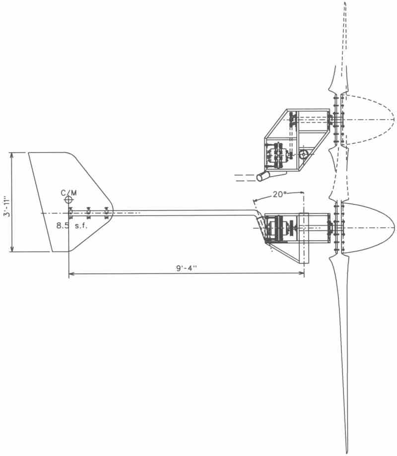
First, I nailed down the finished size of everything...


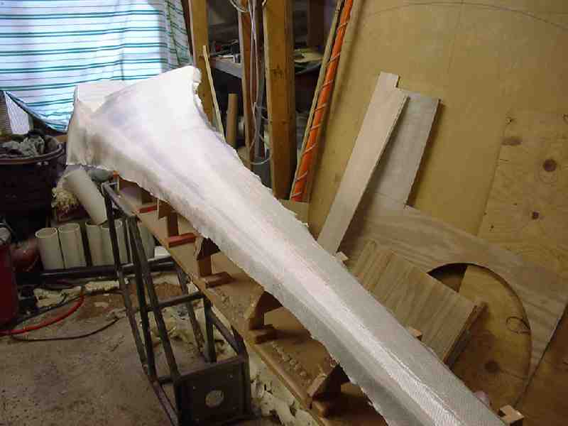
After sanding and filling, I got busy with the fiberglass and resin.


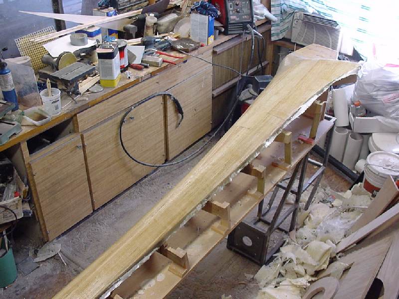
Starting to look like something now.


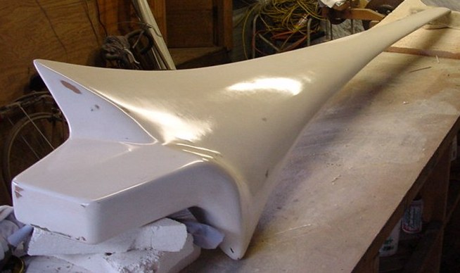
Lets skip ahead, past all the itchy fiberglass sanding, messy gelcoat applications

and dusty gelcoat sanding and go right to the waxing. Ooooohhh!
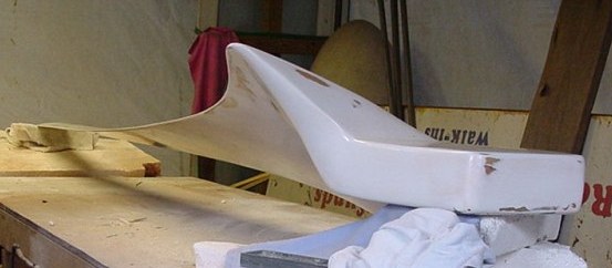


Twist & taper...


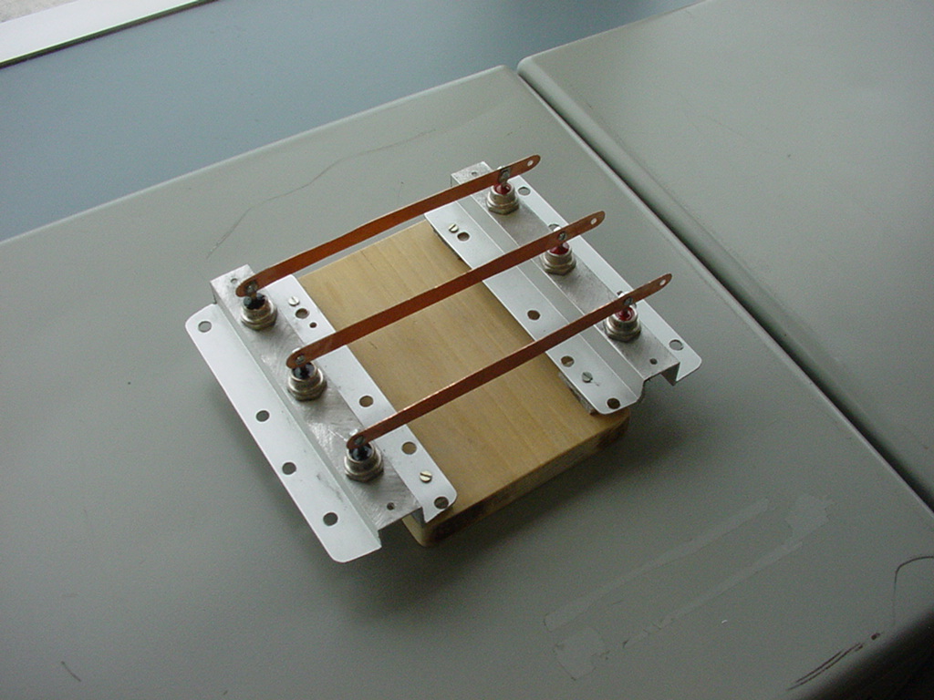
Homade 3-phase bridge rectifier from 6 50A/600V stud diodes and some shop scraps

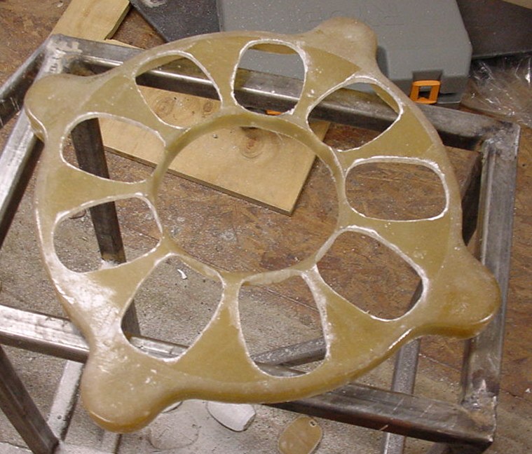
Coil cutouts in the stator plate


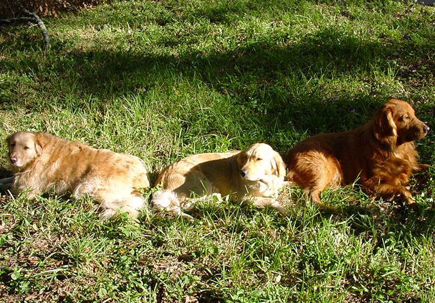
...and as always, the team of project supervisors


The plug is finished and waxed. I am now making the flange or "shadowbox" that goes around the entire periphery. When the gelcoat for the mold proper is sprayed, it and the fiberglass to follow will overlap onto the flange area and be trimmed along the outer edge of the flange. Doing this automatically provides a flange surface for the opposite half of the mold when it is layed up.


The batteries are coming along slowly, testing and charging and cherry picking the best cells to make up new batteries with. Finally found out what "battery oil" was after a good deal of time on the internet- just pure mineral oil from the drug store. Not cheap at $8.00 a quart, which is enough to do 9 cells at the recomended level.

Be safe, be happy & I'll report in again when I get some more done

« Last Edit: April 04, 2007, 01:50:46 AM by (unknown) »

willib

  • SuperHero Member
  • ******
  • Posts: 2414
  • Country: us
Re: Progress Report
« Reply #1 on: April 03, 2007, 08:41:52 PM »
Awesome work there clflyguy

what is going to be the dia of the blades ?

nice work on the bridge rectifier

cute supervisors
« Last Edit: April 03, 2007, 08:41:52 PM by willib »
Carpe Ventum (Seize the Wind)

SamoaPower

  • Sr. Member
  • ****
  • Posts: 417
Re: Progress Report
« Reply #2 on: April 03, 2007, 09:45:21 PM »
Congratulations!

I commend your willingness to not become one of the sheep and fall into the "cast stator" mold (pun intended).


I predict that your risk of stator burn-out will be substantially less as long as you get some air moving past the coils.


I also hope you broke the mold (I gotta stop this) and used a "real" airfoil on that lovely blade.


In any case, congratulations again on the great work. Looking forward to further reports.

« Last Edit: April 03, 2007, 09:45:21 PM by SamoaPower »

clflyguy

  • Jr. Member
  • **
  • Posts: 87
Re: Progress Report
« Reply #3 on: April 04, 2007, 05:44:57 AM »
I'm shooting for 18' plus or minus a couple of the little marks on the tape measure
« Last Edit: April 04, 2007, 05:44:57 AM by clflyguy »

DanB

  • Global Moderator
  • SuperHero Member
  • *****
  • Posts: 2151
  • Country: us
    • otherpower.com
Re: Progress Report
« Reply #4 on: April 04, 2007, 06:42:39 AM »
Beautiful work!

You deserve a prize - I hope that makes lots of power for a long time.  Looks as though it probably will...

Like SamoaPower said - it's nice to see some new approaches.

Can't wait to see the rest of it all.
« Last Edit: April 04, 2007, 06:42:39 AM by DanB »
If I ever figure out what's in the box then maybe I can think outside of it.

clflyguy

  • Jr. Member
  • **
  • Posts: 87
Re: Progress Report
« Reply #5 on: April 04, 2007, 06:49:10 AM »
Hey Samoa,

 Yes, yourself and a few others caused me to give a lot of consideration to the

overheating issues. If I can think of a way to design a thing to last longer,

then thats how it will be made. I'm a belt AND suspenders kind of guy. As you can

see in one of my earlier posts, I didn't fully encapsulate the magnets, there is a

1/8" lip on the rotors for retainage and the resin only comes as high as the lip.

I'm counting on the exposed bodies of the mags to keep the air stirred up in that

area. -The airfoils; I saw in your photos that you also fly R/C, nice bipe hanging up there by the way.. Anyway, the root is a NACA 8413 @ 24.5" chord which continually

and painstakingly morphs to a NACA 4312 @ 4.5" chord at the tip. What airfoil is that on the blade in the rack in your garage? With so much undercamber I assume I'm

looking at the root end? I have a really fast airfoil for tips if you want it-

I didn't use it on this one though.
« Last Edit: April 04, 2007, 06:49:10 AM by clflyguy »

clflyguy

  • Jr. Member
  • **
  • Posts: 87
Re: Progress Report
« Reply #6 on: April 04, 2007, 08:02:29 AM »
Thanks Dan,

But actually I think you guys deserve the prize for this site and being willing

to share your knowledge, experience and ideas. My background is mold building,

industrial and model airplane design and for the last 20 years, CAD. 30 years ago

I took a 1 week welding course in the Coast Guard and then never used it. I had to teach myself all over again. I realize I don't contribute a lot to the board, most

of the time I feel overwhelmed at the level of accomplishment and knowledge represented here. However, I can offer simple, fast and easy methods on hot wiring

foam and virtually anything to do with fiberglassing and mold building.
« Last Edit: April 04, 2007, 08:02:29 AM by clflyguy »

Nando

  • Hero Member
  • *****
  • Posts: 1058
Re: Progress Report
« Reply #7 on: April 04, 2007, 08:04:00 AM »
The blade a master piece


The rectifiers block, DOES need additional surface area for proper cooling and I presume that one set of three are with the diodes Cathode connected to the bolts and the other set with the Anodes connected to the bolts, otherwise you will a just a 3 phase half way rectification.


You did not indicated what the current is going to be, though you said that were from a 50 A, 600 V


If you are going to have around that amp level, the expected dissipation looks close to 40 to 50 watts dissipation which demands close to 60 square inches of surface for proper cooling.


Nando

« Last Edit: April 04, 2007, 08:04:00 AM by Nando »

jacquesm

  • Sr. Member
  • ****
  • Posts: 467
Re: Progress Report
« Reply #8 on: April 04, 2007, 08:35:12 AM »
Amazing work, really impressive.


Is this a two or a three blade machine ?


(I couldn't tell from the drawing and I only see the one blade)


 Jacques

« Last Edit: April 04, 2007, 08:35:12 AM by jacquesm »

clflyguy

  • Jr. Member
  • **
  • Posts: 87
Re: Progress Report
« Reply #9 on: April 04, 2007, 08:43:43 AM »
Hello Nando,

Thank you for the compliment. The diodes are anode mount on one side and cathode

mount on the other. The cooling area of each side of the rectifier is 55 sq. in.

for a total of 110 sq. in.. I hope you did not mean 60 sq. in. per diode, if so

then a re-design seems to be in order.
« Last Edit: April 04, 2007, 08:43:43 AM by clflyguy »

clflyguy

  • Jr. Member
  • **
  • Posts: 87
Re: Progress Report
« Reply #10 on: April 04, 2007, 08:53:19 AM »
Hello Jacques,

Thank you. This is going to be a 3 blade turbine, and what you are seeing is

actually just the original part or "plug" that the blade molds will be made from.

When the top and bottom molds are completed, only then can I make the actual

blade parts.
« Last Edit: April 04, 2007, 08:53:19 AM by clflyguy »

Nando

  • Hero Member
  • *****
  • Posts: 1058
Re: Progress Report
« Reply #11 on: April 04, 2007, 08:59:51 AM »
What is the peak operating expected current ?.


You need around 3 square inches per dissipating watt .


For practical purposes each block can be assumed that dissipates current * (diode 0N voltage) = watts, so if the current is 50 amps and the Diode average voltage is 1 volt the dissipation would be 50 watts or around 150 square inches per side.


Make sure you are using Aluminum heat sink material with long Fins, if possible.


Nando

« Last Edit: April 04, 2007, 08:59:51 AM by Nando »

DanB

  • Global Moderator
  • SuperHero Member
  • *****
  • Posts: 2151
  • Country: us
    • otherpower.com
Re: Progress Report
« Reply #12 on: April 04, 2007, 09:12:14 AM »
Yes, those were my thoughts too - I think you need a lot more surface area.  
« Last Edit: April 04, 2007, 09:12:14 AM by DanB »
If I ever figure out what's in the box then maybe I can think outside of it.

Mary B

  • Administrator
  • SuperHero Member
  • *****
  • Posts: 3178
Re: Progress Report
« Reply #13 on: April 04, 2007, 09:57:16 AM »
I would be a bit concerned with the losses in the steel blades on the rectifiers. Not the best conductor. Copper strip or even small diameter copper pipe would be much better.
« Last Edit: April 04, 2007, 09:57:16 AM by MaryAlana »

clflyguy

  • Jr. Member
  • **
  • Posts: 87
Re: Progress Report
« Reply #14 on: April 04, 2007, 11:14:09 AM »
MaryAlana-

Perhaps the photographs lighting was inadequate to really make it out, but the

blades are copper. As to the insufficient heat sink area, I am ordering one of the

Dan's aluminum heat sinks this afternoon.
« Last Edit: April 04, 2007, 11:14:09 AM by clflyguy »

clflyguy

  • Jr. Member
  • **
  • Posts: 87
Re: Progress Report
« Reply #15 on: April 04, 2007, 11:36:16 AM »
Nando,

I need your help. As I have told you before I am not a very good math or

electronics formula person. I will give you all of the information I can

about this turbine. Perhaps you can tell me what I can expect in current,

voltage and watts? I will be charging a 24V 1020Ah NiCad bank with the turbine

and 3kW of solar panels.


Blade diameter 18'-0"

TSR 9-10

Magnets 24@1"x2"x.5"

Coils 9@ 208 turns 16gage .75" thick

Gear up ratio 2.33:1

Air gap .875" +/- .0312"

Single coil test 13.1VAC @ 300RPM

« Last Edit: April 04, 2007, 11:36:16 AM by clflyguy »

jmk

  • Hero Member
  • *****
  • Posts: 603
Re: Progress Report
« Reply #16 on: April 04, 2007, 01:47:14 PM »
 That sure is some nice work. I think the supervisors disserve a bone! You will have to keep us posted so we can keep up with your progress. How are you planning to hold in the coils, and how are you going to keep them from separating? To me it seems that your alternator is a bit small for that size of a rotor, but I'm no expert.It will be very interesting to see the finished project, and to hear of it's performance.  
« Last Edit: April 04, 2007, 01:47:14 PM by jmk »

ghurd

  • Super Hero Member Plus
  • *******
  • Posts: 8059
Re: Progress Report
« Reply #17 on: April 04, 2007, 01:59:39 PM »
I love the blades!


I'm with Nando on this.  The half wave part.  And Not enough surface area.

It also looks like the AL thickness is kind of "thin".

For heat dissipation, surface area will be related to thickness.


ie: 100 square inches of AL foil is not the same as 25 square inches of 1/2" thick AL plate.


Just a thought.

G-

« Last Edit: April 04, 2007, 01:59:39 PM by ghurd »
www.ghurd.info<<<-----Information on my Controller

jimovonz

  • Sr. Member
  • ****
  • Posts: 339
Re: Progress Report
« Reply #18 on: April 04, 2007, 02:24:35 PM »
Your alt looks too small by quite a long way... 13.1Vac@300rpm/coil = 13.1/300*3*1.414=0.185V/rpm (peak line voltage, 3 x coils in series, delta) This gives a cut in of 24/0.185~130RPM (alt) which equates to 130/2.33~56RPM(blades). 56RPM@TSR9~4mph

Using 3 coils in parallel per phase and connecting in star gives a reasonable cut in around 100RPM/8mph but the power curve of the alt (asuming avg dimension of 2"x3" ~0.7Ohm per coil) falls well short of the power available from the blades.
« Last Edit: April 04, 2007, 02:24:35 PM by jimovonz »

jimjjnn

  • Hero Member
  • *****
  • Posts: 511
Re: Progress Report
« Reply #19 on: April 04, 2007, 06:23:35 PM »
The blades are copper and usually coated with silver or tinned with solder. Most Integrated Circuits are coated with silver. That's one of the reasons after a period of time the IC pins turn black from silver oxide.
« Last Edit: April 04, 2007, 06:23:35 PM by jimjjnn »

kitestrings

  • Hero Member
  • *****
  • Posts: 1376
Re: Progress Report
« Reply #20 on: April 08, 2007, 08:49:34 AM »
Cliffg,


Thanks for sharing your progress.  Your blade "plug" is truly impressive workmanship.  Please contribute updates when you can.  Great stuff.


I have one question.  Back at the top there are a couple of drwings that appear to show a belted, or chain-driven alternator, but down further down it appears you're looking at an axial flux alternator.  I'm confused.


-kitestrings

« Last Edit: April 08, 2007, 08:49:34 AM by kitestrings »

clflyguy

  • Jr. Member
  • **
  • Posts: 87
Re: Progress Report
« Reply #21 on: April 08, 2007, 05:55:35 PM »
Hey Kitestrings,

Right on both counts, it is an axial flux alt and it is gearbelt driven at a

step up ratio of 2.33:1. I went with larger blades to sweep more area and

"regular" size alt geared up due to being in a low wind part of the country.

I use the gear pulleys and belt to get away from maintenance issues with chain

and friction issues with vee belts. I'm doing a lot of things different from

most of the folks on the board. Most people are using resistance elements of

one form or another as dump loads, in my system anything from 1.2v to 23v is

channeled to electrolysers to make hydrogen for the stove, when the battery

bank is full (hard to imagine) the dump load goes back to the electrolysers.

Most folks are casting their stators, my coils are exposed to the air. In no

way am I saying they are wrong, I just think about things a little differently.

« Last Edit: April 08, 2007, 05:55:35 PM by clflyguy »

kitestrings

  • Hero Member
  • *****
  • Posts: 1376
Re: Progress Report
« Reply #22 on: April 08, 2007, 06:58:35 PM »
Cliffguy,


Keep thinking outside the box.  It's what keeps this board interesting.


-kitestrings

« Last Edit: April 08, 2007, 06:58:35 PM by kitestrings »

electrondady1

  • SuperHero Member
  • ******
  • Posts: 3120
  • Country: ca
Re: Progress Report
« Reply #23 on: April 09, 2007, 08:20:32 AM »
clflyguy,

you are an accomplished builder, no doubt!

please elaborated on your hydrogen system.

what methods you propose to control the flow of currant and

what methods safegards you will employ in order to utilize this resource.
« Last Edit: April 09, 2007, 08:20:32 AM by electrondady1 »

clflyguy

  • Jr. Member
  • **
  • Posts: 87
Re: Progress Report
« Reply #24 on: April 09, 2007, 10:18:43 AM »
Hello Electrondady1,

  The hydrogen system consists of 10 electrolysers connected to a controller that switches them on or off based on voltage available up to 24volts. At 24volts a relay is triggered and the power is shunted to the battery bank. There is a manual A-B switch that allows me to shunt the power back to the electrolysers so I can take a reading on the bank voltage. I have a NiCad bank, so other than using a little more water than normal, nothing too bad will happen if I'm not there to switch it over to dump load (electrolyser) mode in the rare case of a fully charged bank. The hydrogen produced is bubbled through two flasback arrestors before being bubbled into a low pressure floating tank collector. when the tank floats high enough, it triggers a mercury switch that turns on a refrigerator compressor that sucks the hydrogen out of the floating tank to such a point that the tank lowers and turns the switch back off. The compressed gas is pumped through a one way valve into LP tanks for high pressure storage and used in the kitchen or grill as a mixture of LP & H2 so the flame remains visible.
« Last Edit: April 09, 2007, 10:18:43 AM by clflyguy »

jacquesm

  • Sr. Member
  • ****
  • Posts: 467
Re: Progress Report
« Reply #25 on: April 09, 2007, 07:12:35 PM »
ah ok, I get it now, that's your master.


very very impressive.


if you can find the time please document as much of the process as possible, you are doing an exemplary job and it's very easy to miss a step that to you seems obvious but that for someone trying to replicate is very hard.


Unfortunately I'm not in a position to do anything with RE right now but that blade...


Maybe you could get it on the centre-fold of playboy :)


j.

« Last Edit: April 09, 2007, 07:12:35 PM by jacquesm »

BT Humble

  • Sr. Member
  • ****
  • Posts: 475
Re: Progress Report
« Reply #26 on: April 16, 2007, 07:54:50 PM »


...when the battery

bank is full (hard to imagine) the dump load goes back to the electrolysers.


That's not so hard to imagine - 560W of solar is plenty for keeping my 24V/1000Ah bank topped off.  


Of course, my biggest load is a bar fridge. ;-)


BTH

« Last Edit: April 16, 2007, 07:54:50 PM by BT Humble »