Author Topic: Step 1 Rotor Design  (Read 2409 times)

0 Members and 1 Guest are viewing this topic.

Nuclear Adams

  • Newbie
  • *
  • Posts: 4
Step 1 Rotor Design
« on: February 10, 2009, 03:10:09 AM »
I plan on building my first Axial Flux machine and I hope for some feedback from the years of knowledge here.  I plan on machining up all of the components that I am able to.  I plan on building the alternator first, then deciding what size blades will be needed based on test results of the alternator.


I am starting with the rotor because I have magnets and steel now.  The magnets are 22.5 degree wedges, 4" ID and 8" OD, N42SH 1/4" thick neodymium.  The rotor material can be 1018 or 4140 since I have plenty of both.  I also have aluminum, but my understanding is that steel will direct the flux much better.  


I plan machining pockets in the steel for the magnets to sit in.  I thought about putting tap holes in the magnets to hold them, but I don't know if that's a good idea.  I have access to an EDM so I could burn the tap holes in, but I'm afraid that this could damage or weaken the magnets.


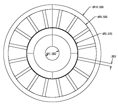
I am trying to keep this compact, so there is not much of a gap between magnets, only about .3"  I have read that this could (will) cause flux leakage, but is it so big an issue that fewer magnets or a larger diameter would make sense?


This is what I had in mind:


I plan on testing a few different coil configurations when I get the rotor(s) completed so I'm hoping that my cart isn't too far in front of the horse at this point.


I have been reading here and several other sites for about 6 months now, but I would have to read for a hundred years to be able to figure this all out on my own.  Please take a moment and let me know what you might change.  It's just on paper right now, there will never be an easier time than now to make adjustments.


My goal is to build a machine to reduce my monthly electric bill.  I don't care if it costs a bit, I'm really not concerned about "payback time" since this will be part money saving, part being green, part fun, and part giving me something to tinker with when it's too cold or hot to be outside.


Thanks!

« Last Edit: February 10, 2009, 03:10:09 AM by (unknown) »

Flux

  • Super Hero Member Plus
  • *******
  • Posts: 6275
Re: Step 1 Rotor Design
« Reply #1 on: February 10, 2009, 01:52:05 AM »
With those thin magnets you don't want to put them into a hole. With magnets 1/2" thick or more setting them in a bit doesn't loose you that much. At only 1/4" thick you will loose a lot. Regards putting holes in them, it may be ok but you will damage the protective coating and eventually I suspect you will start corrosion problems. I can't imagine that EDM will do much damage otherwise, but it is not something I would do.


You seem to have good machining facilities so the simplest way would be to stick them on the steel plates and you could machine an annular ring of aluminium to go outside the magnets to prevent them flying out ( which they won't do anyway if you use a good structural adhesive, not superglue crap).Screw the annular ring to the steel disc. Alternatively you could use a stainless band round the outside of the disc as DanB does. You won't get much fanning effect from thin magnets so there is no real reason not to pot them in resin which will give added support and weather protection if you are in a damp area.


Your very close spacing is going to loose you a lot of winding space. It better suits a 2layer winding with overlapped coils ( bit close spaced even for that). For the single layer winding you would do far better with spaces about magnet width. Why does compactness matter? Basically the larger the better for use of magnets and for surface area to dissipate stator heat. If I wanted a compact alternator I would have gone for far thicker magnets.


There will be some leakage flux with close spaced magnets but basically the big issue is that you restrict the winding area for your coils and will need thin wire with very high resistance. The leakage flux issue becomes more of a factor if you try to use large gaps. with those thin magnets you ought to be working with an air gap 3/8" thick but that gives very little winding space when you waste at least 1/16" on either side for mechanical clearance. At best it only leaves room for 1/4" thick coils and you will have 60% unwound if you make the hole magnet size.


Personally I would increase disc size to space the magnets about magnet width and I would work with 1/2" air gap and try for coils 3/8" thick. Even so it won't take a very big prop so start thinking of test coils to suit the cut in speed of perhaps a 7ft prop as a starting point.


Flux

« Last Edit: February 10, 2009, 01:52:05 AM by Flux »

electrondady1

  • SuperHero Member
  • ******
  • Posts: 3122
  • Country: ca
Re: Step 1 Rotor Design
« Reply #2 on: February 10, 2009, 07:04:27 AM »
 what about a second rotor ?

it would open up the mag spacing as flux suggests .

place 8 mags on one rotor and 8 on the other.

a dual rotor axial flux alternator .

it would be a more powerful layout than your present proposal.
« Last Edit: February 10, 2009, 07:04:27 AM by electrondady1 »

Flux

  • Super Hero Member Plus
  • *******
  • Posts: 6275
Re: Step 1 Rotor Design
« Reply #3 on: February 10, 2009, 08:02:26 AM »
I took it as though he was intending to make it 16 pole dual rotor. if it is intended to be single rotor then it will be very disappointing.


Flux

« Last Edit: February 10, 2009, 08:02:26 AM by Flux »

electrondady1

  • SuperHero Member
  • ******
  • Posts: 3122
  • Country: ca
Re: Step 1 Rotor Design
« Reply #4 on: February 10, 2009, 08:10:27 AM »
???

perhaps it's just my interpretation.
« Last Edit: February 10, 2009, 08:10:27 AM by electrondady1 »

Nuclear Adams

  • Newbie
  • *
  • Posts: 4
Re: Step 1 Rotor Design
« Reply #5 on: February 10, 2009, 11:20:54 PM »
Thank you so much for your observations.


I wanted to recess the magnets and screw them in because I plan on having the plates powder coated and I have a little concern about the coating peeling off under the magnets. I like the idea of the aluminum ring around the outside of the magnets. I have seen the stainless bands and think it's a great solution, but I'm not sure that I could get everything mounted perfectly.


The reason I was trying to maintain the diameter is because I only have a 10" lathe, but I can get a little more out of it to go 10.5" or so. I can machine a larger disc with a vertical mill, but I would have to do it with a turntable since I only have 9" of travel in one direction.


I do plan on having a pair of rotors as you suspected and have been thinking about maybe even 4 (actually 3, the center one would have magnets on two sides, but I would have to research that some more)


I have redrawn the rotors to fit on a 15" plate. If I go any larger than that I would have to buy them and I would really rather do it myself. The turntable that I can borrow would not allow me to go any larger than that and still reach the handle to turn it. I have also figured in 1/2" thick magnets, but I will have to buy them. This will give me a 1.71" gap between magnets if I stick with arcs rather than rectangles..  


Here is a picture of the new configuration:


And a side view:


I also plan on adding a generous amount of cooling holes, but I will not draw them in until I get closer to a final design.  I also thought of adding fins to the aluminum ring to direct air toward the coils, but again, I will not add that in until I'm much closer if I do it at all.

« Last Edit: February 10, 2009, 11:20:54 PM by Nuclear Adams »

Flux

  • Super Hero Member Plus
  • *******
  • Posts: 6275
Re: Step 1 Rotor Design
« Reply #6 on: February 11, 2009, 01:36:33 AM »
The larger disc looks far better for a single layer winding. I understand your lathe restrictions but going to larger diameter is far more effective than cascading rotors and stators.


Probably best to aim for coils about 3/8" thick to work in an 1/2" air gap. Look at cut in speeds for 7 to 8ft size props and do your test coil. See what size wire you can get in and I would make the holes a bit smaller than the magnets. Probably keep the hole length that of the magnet, you could try both a wedge shape hole and a rectangular one with the hole width that of the magnet smallest width. I am inclined to think the rectangular coils will get you lower resistance even if they need a few more turns for the same voltage.


Air holes, fans etc is something that has been discussed a lot but I don't think there is a lot of practical data. You can probably get air in from the back but not through the front face with prop in the way ( if you live in a wet area I don't like the idea of drawing rain in from the front anyway.I suspect with only an 1/2" air gap the only place for fans is in the inner radius inside the stator, although the speed is low there if you can induce air movement the rest of the disc may drag it through. May not make a fantastic difference but it won't hurt.


Flux

« Last Edit: February 11, 2009, 01:36:33 AM by Flux »

Crusader

  • Newbie
  • *
  • Posts: 17
Re: Step 1 Rotor Design
« Reply #7 on: February 11, 2009, 09:16:54 PM »
Windstuffnow.com has something similar to what you are doing. Maybe it will help.
« Last Edit: February 11, 2009, 09:16:54 PM by Crusader »

Nuclear Adams

  • Newbie
  • *
  • Posts: 4
Re: Step 1 Rotor Design
« Reply #8 on: February 14, 2009, 02:45:37 AM »
Thank you Flux,


My thoughts on the coils involve some fuzzy logic.  Basically, I am fuzzy on the logic :)  I plan on starting out with couple of coils of #24 wire, 30 turns per coil and see what it gets me.  I am thinking #24 wire because I hope to be able to get up to 3Kw from this and 3000W/120V/12 coils = 2.777amp/coil @120V.  I used 120 as the divisor voltage only because my chart is for 120V circuits, my "logic" tells me that the real factor is watts and that can be any combination of Volts X Amps that equal 3000 (although I can't imagine 3000V @1 amp going through #24 wire)  This will at least give me a starting point and the worse that can happen is me getting filthy rich taking all that wasted magnet wire to the recyclers when I burn it up.


As for the idea about cooling, I was talking about adding grooves in the outer ring to draw air out of the center area creating lower pressure which would draw air in through the eventual cooling holes on the rotors.


Isometric view:


I'm not sure how much this will help if at all, but I'm pretty confident that it will not hurt anything.

« Last Edit: February 14, 2009, 02:45:37 AM by Nuclear Adams »

Nuclear Adams

  • Newbie
  • *
  • Posts: 4
Re: Step 1 Rotor Design
« Reply #9 on: February 14, 2009, 02:47:29 AM »
Thank you Crusader, I will take a look!
« Last Edit: February 14, 2009, 02:47:29 AM by Nuclear Adams »