Author Topic: Using Caps on a Wind Genny  (Read 7394 times)

0 Members and 1 Guest are viewing this topic.

ruddycrazy

  • Hero Member
  • *****
  • Posts: 519
Using Caps on a Wind Genny
« on: September 23, 2008, 08:47:07 AM »
Hiya Guy's,

           Over here in Oz we have a raging debate going over the use of caps on a wind genny. I used on my setup 2 off 470uf @400 volt electo's, put them back to back to make them unpolarised then put 3 sets of them on my genny input 1 set set on each phase. Before I used the caps the best I saw on my 24 volt shed array was 10 amps out of the genny, then I put the caps in and sure enough when the next gust of wind came along I saw about 18-19 amps @ 25.8 volts. Gordon (GWatPE) is a good friend and cameup up to my farm last sunday and later went home and replicated my setup. The following link is to a backshed post where further down the page Gordon shows the increase in a more technical nature.


http://www.thebackshed.com/Windmill/FORUM1/forum_posts.asp?TID=1138&PN=1&TPN=4


Now the big question is how would this setup go on other types of Wind Gennies as if it works it could mean a greater input from a genny at little or no extra cost.


Some good advise has come out and that is if you try this make sure your system has the furling setup correctly as if the caps do fail the genny will overspeed and self destruct.


Cheers Bryan

« Last Edit: September 23, 2008, 08:47:07 AM by (unknown) »

Flux

  • Super Hero Member Plus
  • *******
  • Posts: 6275
Re: Using Caps on a Wind Genny
« Reply #1 on: September 23, 2008, 03:57:19 AM »
Alternators are affected by the type of load. Armature reaction ( the effect of the magnetic field from the current in the windings) affects the main field. Inductive loads result in the armature reaction being demagnetising and reduces current output.


In theory resistive loads only distort the field, but as saturation normally occurs somewhere there is usually still a demagnetising effect. Capacitive loads produce a magnetising armature reaction and the increase in field will result in increased output, although the inductive reactance is still effectively in series you will benefit from the higher initial emf.


Air gap machines with no iron will have a small armature reaction and will never reach the reactance limiting stage. The effect of adding capacitors to the air gap axial machines will be no significant gain in magnetic field and your stator has to carry the reactive current with more drop.


Use capacitors with iron cored machines especially those with seriously high leakage reactance and you will benefit. Don't bother with axial air gap alternators it won't help and may hinder.


The ideal solution for the F& P and other highly reactive machines is to include the capacitors in series with the windings. If you can achieve resonance with the inductive reactance the reactive component is neutralised and only the resistance remains. Not really practical for wind but it may be a useful dodge with hydro where you run at constant speed and can maintain resonance.


Flux

« Last Edit: September 23, 2008, 03:57:19 AM by Flux »

oztules

  • Hero Member
  • *****
  • Posts: 1477
  • Country: aq
  • Village idiot
Re: Using Caps on a Wind Genny
« Reply #2 on: September 23, 2008, 05:26:54 AM »
Flux,

whilst I understand your argument, your conclusion does not seem to be born out in real world testing.

These graphs would seem to indicate that a vast improvement for wind application is apparent with this style of high pole count alternator.


Here is the data of relevance as explained by the experimenter


"This is a comparison of before and after series caps on a 100S F&P in delta.


The comparison should be interpreted as the change in the ratio of the average of the F&P in yellow to the axial flux in purple. The F&P has 50% larger swept area.


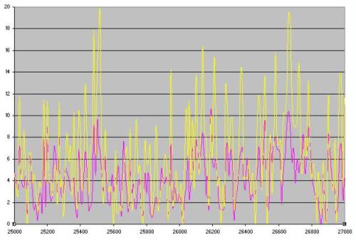
Thge first graph is before caps with maximiser and the second shows the change in the yellow graph[F&P with caps], without maximiser. The ratio of the average of the data is the important detail."


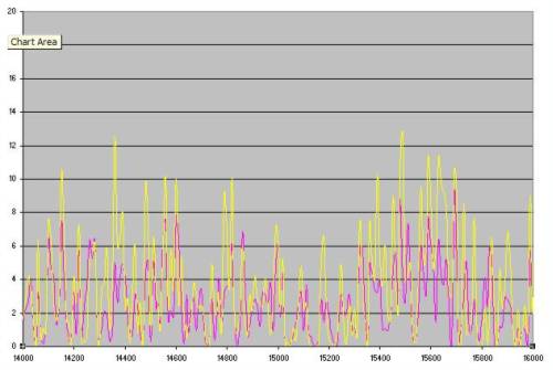
"The ratio in the first graph is 1.33

The ratio in the second graph is 1.46


The caps provide a better increase in average power than a boost maximiser.


There is a significant increase in the maximum power output, by almost a factor of 2. This would be of more use in stronger wind conditions.


A combination of capacitors and boost maximiser will be looked at next.


This should give benefit at the top and bottom of the windspeed range.


More to come.


Gordon.


PS


The graphs are battery current vs time, for the same timing period. The wind conditions had changed, but the 2 windmills were operation in the same winds, with no wind shadowing and are only 6m apart."


===================

The yellow is the F&P, and the pink is the axial flux alternator used as a reference.... 6 meters apart


Faced with this result, I think your conclusion "Not really practical for wind but it may be a useful dodge with hydro where you run at constant speed and can maintain resonance."   is difficult to comprehend.


I would have thought an increase of that magnitude is worthwhile, and would certainly be applicable to wind. It also seems to stop the mill going into runaway at 10 or so amps... which alone is very worthwhile.


It seems to me that getting some improvement in some parts of the spectrum, and massive improvement in other parts is worth pursuing, stopping runaway and getting a vast improvement in power where non at all was available before (because of reactance limiting at 11A) is a worthwhile gain, The caps seem to  turn a very average device into a reasonable device.... (I'll stick with axials myself however)


........mystified with your conclusion here


........oztules

« Last Edit: September 23, 2008, 05:26:54 AM by oztules »
Flinders Island Australia

fungus

  • Sr. Member
  • ****
  • Posts: 448
Re: Using Caps on a Wind Genny
« Reply #3 on: September 23, 2008, 05:40:28 AM »
"Faced with this result, I think your conclusion "Not really practical for wind but it may be a useful dodge with hydro where you run at constant speed and can maintain resonance."   is difficult to comprehend."


As far as I see it, that comment was directed towards using capacitors in series with the windings?

« Last Edit: September 23, 2008, 05:40:28 AM by fungus »

oztules

  • Hero Member
  • *****
  • Posts: 1477
  • Country: aq
  • Village idiot
Re: Using Caps on a Wind Genny
« Reply #4 on: September 23, 2008, 05:48:38 AM »
Of little relevance to the above......


It is interesting how well the booster was operating in graph 1 (it cuts off after 2A I think). At no time was the power output below the axial.


In graph 2, the F&P without the booster fell below the axial on many occasions (I assume lower freq hurt the capacitive coupling). I wonder if greater than 1.46 would have been achieved if the booster had have been there to hold the lows at a higher level.


........oztules

« Last Edit: September 23, 2008, 05:48:38 AM by oztules »
Flinders Island Australia

oztules

  • Hero Member
  • *****
  • Posts: 1477
  • Country: aq
  • Village idiot
Re: Using Caps on a Wind Genny
« Reply #5 on: September 23, 2008, 06:05:49 AM »
Hi Fungus,

The second graph is with caps in series with the windings..., and without the boost converter.


.........oztules

« Last Edit: September 23, 2008, 06:05:49 AM by oztules »
Flinders Island Australia

Flux

  • Super Hero Member Plus
  • *******
  • Posts: 6275
Re: Using Caps on a Wind Genny
« Reply #6 on: September 23, 2008, 07:13:04 AM »
Sorry I haven't been following what you are doing in Australia, the F & P is not available here so there is no interest in it.


I assumed from the description that the capacitors were added across the phases ( as in a power factor correction system). As I said there will be a large improvement with a high reactance alternator and if the gain in emf from armature reaction addition of flux if sufficient to allow you to change from star to delta will make a spectacular improvement as you are reducing the impedance by a factor of 3 ( including the resistive bit and that is where most of your gain is coming from).


In this case the capacitors are not resonant and are not removing the reactive component. With series capacitors in a star configuration you can at one frequency cancel the reactive component. It will work over a small range of speeds and even with speeds over the resonant value it will still bring the load power factor leading and will still give the same effect as the shunt capacitors. This may still be worth trying with wind but the capacitors need to be very large for low voltage systems and would probably need to be electrolytic back to back.


I would have doubts about the initial cost and long term reliability but if the gain is great enough then it may even be worth spending a large sum on non- polarised capacitors.


Some of these arguments will also apply to motor conversions, especially to those with low flux levels. If you can get away with less magnet you reduce iron loss drag and get easier start up, if you can increase the flux level with capacitors then you are on to a good thing but again all these schemes work far better at high voltage. The frequency of motor conversions will need capacitor values that are not really practical. At least the F&P has a large pole count and starts with a reasonable frequency so capacitor values are more modest.


Flux

« Last Edit: September 23, 2008, 07:13:04 AM by Flux »

electronbaby

  • Sr. Member
  • ****
  • Posts: 407
  • Country: us
    • Windsine.org
Re: Using Caps on a Wind Genny
« Reply #7 on: September 23, 2008, 07:59:16 AM »
It appears as if you are playing against the reactance of the feed line. It would be interesting if tests were done with the caps located at the turbine, and at the rectifier, however, the overall outcome will probably average out to be the same.


In these tests that are being done in Australia, what type and size of feed lines are being used? How long a run is it? in Ohms?

« Last Edit: September 23, 2008, 07:59:16 AM by electronbaby »
Have Fun!!!  RoyR KB2UHF

oztules

  • Hero Member
  • *****
  • Posts: 1477
  • Country: aq
  • Village idiot
Re: Using Caps on a Wind Genny
« Reply #8 on: September 23, 2008, 08:52:28 AM »
Check that link in Bryans comment. The waveforms are of interest. There are high voltages and frequencies involved with this style of stator, (50 something magnets apparently and 40 something coils) and I am just now beginning to suspect things other than power factors and inductive reactance difficulties are involved here.


There seems to be a genuine current conversion going on in the caps. I am wrestling with the theory that the gap in the square wave is possibly held open by the other two phases for a brief period, giving the cap time to accumulate some electrons, which get discharged a little bit later on in the form of higher current burst. There is an abundance of voltage in the coils. For a 24v system, the coils are up around 60v rms apparently.


I have no idea... but something is happening that is certain.... but still clutching at straws at the moment.


.........oztules

« Last Edit: September 23, 2008, 08:52:28 AM by oztules »
Flinders Island Australia

Flux

  • Super Hero Member Plus
  • *******
  • Posts: 6275
Re: Using Caps on a Wind Genny
« Reply #9 on: September 23, 2008, 10:12:24 AM »
Ok I have read it briefly. He does say that the capacitors are in series so in that case there will be a resonant point where the capacitive reactance neutralises the inductive leakage reactance. At that point the current will be dictated by the winding resistance just as for an axial air gap machine and the characteristics should be similar. Without this those alternators become reactance limited and no matter how fast you run them the current will eventually become constant. The thing starts to curve over when R becomes equal to Xl. as Xl dominates the reactance rises with frequency and it goes into constant current mode like a bike dynamo.


If you can get things right then the alternator load will increase with speed instead of levelling off and if you can track that to the prop characteristic then you will gain enormously. I suspect that if the wind gets high enough and you go beyond resonance the capacitive reactance will be small and the thing will revert back to inductive reactance limiting and it might let the prop run away.


There will be plenty of volts flying about at this resonant point and it will be similar to a motor starting circuit for single phase. Watch the capacitor volts, at resonance you may go well above anything you expected.


If you get this right then you overcome the most serious disadvantage of these long pole iron core machines which were intended as synchronous motors and are not ideal as alternators.


Play with the capacitor values they may well be quite critical for best results.


Flux

« Last Edit: September 23, 2008, 10:12:24 AM by Flux »

tecker

  • SuperHero Member
  • ******
  • Posts: 2183
Re: Using Caps on a Wind Genny
« Reply #10 on: September 23, 2008, 10:56:47 AM »
The series Caps work while running caps around the same rating would not . You can see from the wave form what is hppening the voltage rises to a spike before leakage to the other cap in the series string starts and the combined charge starts to accumulate just before the current flow . If you put running caps in there they would discharge slowly and screw with the current flow lagging the current by 30 to 40 degrees . This spike and light discharge puts you up on voltage and current you can see the current as it flattens the sine on the backside .
« Last Edit: September 23, 2008, 10:56:47 AM by tecker »

tecker

  • SuperHero Member
  • ******
  • Posts: 2183
Re: Using Caps on a Wind Genny
« Reply #11 on: September 23, 2008, 11:00:50 AM »
Very good data and nice mod I assume those were both 230 mike electrolitics
« Last Edit: September 23, 2008, 11:00:50 AM by tecker »

Ungrounded Lightning Rod

  • SuperHero Member
  • ******
  • Posts: 2865
Re: Using Caps on a Wind Genny
« Reply #12 on: September 23, 2008, 01:39:25 PM »
Capacitors in series means the load is zero at startup and rises with speed (up to resonance).


Perhaps part of the gain is from getting the turbine out of stall?


I'd like to see the frequency or RPM versus wind speed for both configurations.


I'd also like to see how the genny, caps, instruments, and load were connected.  I wouldn't expect caps in SERIES to smooth out the waveform.


(Meanwhile my first attempt at a conversion will probably be putting some magnets into a variable-speed motor I salvaged from a Maytag Neptune.  I think I'll play around with caps to see if I can get more out of it or get it to run in a better mode, once I've gotten it converted.)

« Last Edit: September 23, 2008, 01:39:25 PM by Ungrounded Lightning Rod »

zeebag

  • Newbie
  • *
  • Posts: 7
Re: Using Caps on a Wind Genny
« Reply #13 on: September 24, 2008, 03:13:22 PM »
You got a nice friend. Were those indeed 230 mike electronics?
« Last Edit: September 24, 2008, 03:13:22 PM by zeebag »

oztules

  • Hero Member
  • *****
  • Posts: 1477
  • Country: aq
  • Village idiot
Re: Using Caps on a Wind Genny
« Reply #14 on: September 24, 2008, 04:34:18 PM »
The two 470uf electro capacitors are back to back in series to give a 235uf bipolar electro.


Whether this is the ideal value for this setup has not been properly established yet, seems to work well. I believe more testing with other values is yet to come.


........oztules

« Last Edit: September 24, 2008, 04:34:18 PM by oztules »
Flinders Island Australia

Flux

  • Super Hero Member Plus
  • *******
  • Posts: 6275
Re: Using Caps on a Wind Genny
« Reply #15 on: September 25, 2008, 01:04:39 AM »
I am not convinced that you halve the value when using these back to back, that assumes that both remain capacitors. I suspect that the reversed polarised one may not contribute capacitance and that the effective value may be nearer the 470.


Not that this matters much as you will probably not be able to calculate the leakage reactance of the winding.


Flux

« Last Edit: September 25, 2008, 01:04:39 AM by Flux »

oztules

  • Hero Member
  • *****
  • Posts: 1477
  • Country: aq
  • Village idiot
Re: Using Caps on a Wind Genny
« Reply #16 on: September 25, 2008, 01:58:28 AM »
This conversation was had here in about 2006.


After some discussion, between Samoapower and ULR, I think it became clear that ULR knows his stuff on this one.


I am certain his final conclusion was


  1. It does not double the voltage
  2. It does halve the capacitance


He also clearly explained the non-use of resistors and diodes in this configuration..... don't use either.


I remember the reasons were compelling, but don't recall much except that the asysmmetric leakage does away with the diodes, and the resistors were a dead loss.


Hopefully I have recalled correctly. Correct me please ULR if I have botched this up.


...........oztules

« Last Edit: September 25, 2008, 01:58:28 AM by oztules »
Flinders Island Australia

ruddycrazy

  • Hero Member
  • *****
  • Posts: 519
Re: Using Caps on a Wind Genny
« Reply #17 on: September 25, 2008, 02:18:42 AM »
Hi Flux,

        I have about 38 of these brand new 400 volt 470uf caps and I used my fluke 865 dmm to test the caps until I found 6 that matched within 5uf. When I soldered some wire on them to make them back to back I got a reading of 216uf on 2 sets and 218uf on the third. The parrallel method was used upto the time I did mine and for me it was too much work to do them that way so I just put them in series to see how'd they go. About an hour or so later the genny really started spinning and man did the current guage rise :). So then I took the caps offline and watched the current guage and only saw 3-4 amps at best. When I re-hooked the caps up and swichted off the short switch the genny kicked in nicely and I saw 10 amps. Since then I've left them on and on some nights when I get home from work and go straight up to my shed my nichrome dumpload is still either warm or glowing if the wind is blowing. Now with my 700ah 24 volt array I have a RossW shunt regulator set to dump at 28.2 volts so for that dumpload to be warm I'd say those caps on the genny are doing the job nicely where without them my batteries wouldn't see the benefit of the genny unless we had gale force winds. Just to let you know I'm a Mechanical Fitter by trade with no formal electronic or electricial training and anything I know in that regard is all self taught. Since we bought the offgrid farm near 5 years ago I feel I've come along way learning what I can in the RE field and I still consider myself a novice.


Regards Bryan

« Last Edit: September 25, 2008, 02:18:42 AM by ruddycrazy »

Flux

  • Super Hero Member Plus
  • *******
  • Posts: 6275
Re: Using Caps on a Wind Genny
« Reply #18 on: September 25, 2008, 08:30:04 AM »
Bryan

I think I may be wrong about the capacitor values and that you will get half as you get with the meter. On second thoughts the mean charge on both stays at half and neither ever gets out of forward bias so they will add in series. If either looses forward bias this will not be true but I doubt that they would last long in that mode.


At best capacitors in parallel will only give a modest improvement, permanent magnets behave as air gaps and the effect of armature reaction is not great.


With them in series you have found a way to overcome the serious limitation of that type of alternator. The resonance will drastically increase the output. I initially thought that off resonance it would be no use but wind requires low levels of load in low winds and the fact that it is off resonance gives you a better match to the prop in those light winds.


In its natural state The F & P is pretty hopeless, you have maximum loading when you least need it and when you really need the load then it goes reactance limited and sheds load ( reverse of what is needed for wind).


As long as the capacitors prove reliable then you are on a winner. Good luck and keep experimenting to find the best possible match.


Flux

« Last Edit: September 25, 2008, 08:30:04 AM by Flux »

GWatPE

  • Newbie
  • *
  • Posts: 48
Re: Using Caps on a Wind Genny
« Reply #19 on: September 25, 2008, 04:07:32 PM »
Hi All,


I had no idea some of my stuff had been referred to here.  


The capacitors were indeed 470uf @ 180WV back to back electolytic in series with the output wiring.  


There is a lot of technical jargon and theories presented.  The capacitors develop AC voltage across them that increases with the rpm and power.  The capacitors seem to work in conjunction with the rectifier diodes to convert high voltage, low current to low voltage and high current.  The windings on my mill produce approx double the AC voltage, but the battery only sees the extra current at the same voltage.  I suspect that any AC generator used in a windmill will see an increase in power related to the decrease in current in the windings as well as some other flux limiting problems in iron cored machines.  


I particularly see the ironless design benefiting from AC coupling, with the removal of the DC component when these machines are connected to a battery load.  This could allow the current that causes heating in the stator at high power levels to be decreased, as the capacitor/diode combination performs a Vi > vI conversion.


I do agree that large pole count machines will benefit most, as capacitor size decreases with increasing frequency.  Inductance determines the suitability of the arrangement.  Mathching inductance and capacitance to the rotor speed with the right pole count will give the best result.  I suspect that a change in axial flux design may be needed to benefit from the adition of capacitors.  I will be testing my own dual rotor 4phase[0.8ohms,independent outputs]mill, 11pole pairs with 3mm air gap [450W 24V machine], as described on another thread, with capacitors.


I do not intend trialing all cap values.  My F&P mill, 2.4m rotor, side furling, works well with the 230uF series caps and digital [variable] boost cct, after I twisted the poles to reduce cogging and startup torque.  


I suspect this will be the start of a significant alternative to an electronic wind MPPT.


Gordon.

« Last Edit: September 25, 2008, 04:07:32 PM by GWatPE »

LeissKG

  • Newbie
  • *
  • Posts: 17
Re: Using Caps on a Wind Genny
« Reply #20 on: September 27, 2008, 02:00:08 PM »
If you use electrolytic capacitors on AC you should take some precautions. What I have learned as an apprentice is that you should NEVER use more than 30 to 50 % of the rated Voltage in AC applications. Here I mean peak voltage in your circuit to rated voltage. Another point is that a high ripple current accelerates the failure rate of the capacitor. Depending on the capacitor the rated values are guaranteed for something of 1000 to 8000 hours. This means the optimal capacitor values that you found through experimentation will slowly creep away. So you either change your capacitors ever so often or invest in an AC capacitor.


Klaus Leiss


« Last Edit: September 27, 2008, 02:00:08 PM by LeissKG »

GWatPE

  • Newbie
  • *
  • Posts: 48
Re: Using Caps on a Wind Genny
« Reply #21 on: September 29, 2008, 12:30:23 AM »
The electrolytic caps are rated at 180WV.  The maximum voltage has been 40VAC.  A five fold margin.  The final version will have AC caps with a 10 fold voltage margin.  The 200Hz maximum operating frequency is the killer for AC caps.


Gordon.

« Last Edit: September 29, 2008, 12:30:23 AM by GWatPE »

Flux

  • Super Hero Member Plus
  • *******
  • Posts: 6275
Re: Using Caps on a Wind Genny
« Reply #22 on: October 02, 2008, 01:08:22 PM »
not sure if anyone will see this here but I see that this thing is still raging on the Australian site.


You are getting there, the shunt capacitors will give only slight improvement.


Series capacitors are the answer and it comes down to cancelling the LEAKAGE reactance.


This is not the winding inductance that you would measure from the machine terminals, a perfect alternator would have inductance measurable from this point of view but would not have LEAKAGE reactance.


With most machines the leakage inductance is tiny but with the stupid construction of the F & P it will be large.


It is a difficult thing to measure as you have to separate leakage reactance from synchronous reactance that includes the effects of armature reaction. I think your contributor Herbenz( or similar if I remembered it wrongly) has got to grips with this.


You can probably best find this value from the resonant frequency with the capacitors and it may be an order of magnitude less than the measured terminal inductance. If you can find it's true value then some of the calculations may start to give sensible results.


Have fun.


Flux

« Last Edit: October 02, 2008, 01:08:22 PM by Flux »

oztules

  • Hero Member
  • *****
  • Posts: 1477
  • Country: aq
  • Village idiot
Re: Using Caps on a Wind Genny
« Reply #23 on: October 02, 2008, 10:47:09 PM »
Flux,

I have yet to find how the caps in series actually change the rotor/stator MMF as Herbnz has described.


Are you able to cover this aspect.... in simple terms... or any terms?


I have thought I had come to grips with this so may times, and every time I think I have got it.... I aint got it...


I have been off with the pixies chasing the wrong inductive reactance. I found your earlier discussion with Bobg very imformative.... and all I can say is this stuff is hard for me to come to grips with.


If I can get to understand how the MMF gets altered with the caps, then I think I may be getting closer to understanding it better..... and what are the main determining factors that will increase/decrease inductive leakage...


Puzzled as always

............oztules

« Last Edit: October 02, 2008, 10:47:09 PM by oztules »
Flinders Island Australia

Flux

  • Super Hero Member Plus
  • *******
  • Posts: 6275
Re: Using Caps on a Wind Genny
« Reply #24 on: October 04, 2008, 06:05:35 AM »
This is getting a bit deep. If trained engineers can't explain it then I am not sure I can but I will try.


You start with your main exciting field and this induces an emf into the stator. If you connect the stator to a load then a current will flow. The current flowing in the turns of the stator will also produce a magnetic field and the two interact this stator field is known as armature reaction. If the main field is strong and the armature reaction small then the machine will have good regulation and the generated voltage will change little with load. This is how they had to build machines before the days of voltage regulators. It is costly to provide the strong field and large air gaps were usually used to keep the armature reaction small.


With the introduction of voltage regulators it became common practice to keep air gaps small and the armature reaction acting through a much smaller air gap had far more effect on the terminal voltage. The no load volts may be 50% higher than full load but the regulator altered the main field to keep terminal volts constant. Results are a smaller and cheaper machine and one that has significant leakage reactance and could survive a sudden short ( shouldn't happen but does sometimes and if the machine can survive then it is a great asset)


Now the tricky bit and here I may struggle. I think that the armature reaction for a resistive load acts in quadrature to the main field. It will strengthen the field on one side of the main pole and weaken it on the other side. Neglecting saturation the total flux doesn't change and the emf is not affected ( terminal volts will fall due to impedance).


If the load is inductive then the armature reaction becomes demagnetising and the emf falls with load. When you add in impedance the terminal volts may fall drastically.


If you make the load current leading ( capacitive load and it can be series or shunt capacitance) then the emf will rise with load (armature reaction magnetising). If the impedance is low then the terminal volts can rise with load as well. The thing that limits this in conventional machines is core saturation. If the main field is strong and the core nearly saturated the rise may be small. If it has a small air gap and is running with low flux then the rise can be spectacular and many small alternators will self excite out of control of the voltage regulator into a very capacitive load.


The effect on emf with permanent magnets is far less marked than with wound field machines with iron poles as the magnet material is essentially saturated and acts much like air as far as armature reaction is concerned.


That is why shunt capacitors give little improvement. Series capacitors behave the same as far as the emf is concerned but at resonance the capacitive reactance cancels the lagging inductive leakage reactance and just leaves you with resistance.


The F & P has long salient poles on the armature and this is the worst possible configuration for leakage inductance. The armature reaction forces the main field to fringe sideways between poles rather than keep to the intended route and much of the flux fails to link all of the stator winding. As well as cancelling the leakage inductance the capacitively loaded stator has the best chance of maintaining the main flux in the intended direction. The rise in emf may be small but the leading power factor will give a lower leakage inductance.


Hope this helps. If your maths is good enough to understand 2 axis machine theory you may find the answers in the equations of the generalised machine, but it is Greek to me. Perhaps it is because I can't do the maths that I have to get to understand this from a more practical angle and if I managed to explain it well enough it may help you as well.


Flux

« Last Edit: October 04, 2008, 06:05:35 AM by Flux »

oztules

  • Hero Member
  • *****
  • Posts: 1477
  • Country: aq
  • Village idiot
Re: Using Caps on a Wind Genny
« Reply #25 on: October 04, 2008, 07:20:43 AM »
Thanks very much for taking the time to explain it as best you could to a neophyte like me.


I have spent the intervening period trawling through difficult to follow screeds from engineering books on the net. But alas, they use more greek letters than I thought were actually in the alphabet.


However, from what I was able to glean ( and it wasn't lots and lots) you explanation sews it all together as good as it gets I think (and in understandable terms as well).


It has been a long journey with many mind changes, dead ends, wrong assumptions and generally flailing about in a vacuum, but happily I think I have a decent grasp on it now. It does satisfactorily explain a lot of what I have witnessed along the way.


I did find a use for those people who insist on measuring the short circuit current. It turns out that the ,

synchronous impedance =open circuit voltage/short circuit current


From that we find that synchronous reactance (Xs) =root Zs sq- Ra sq .... Ra is the resistance of the stator... but I don't see an easy way to get the XI separated from the XA..... so this is the end of theory to calculate the best caps at this stage.


At least we now know the problem is real and practically solvable.


Thanks again


.........oztules

« Last Edit: October 04, 2008, 07:20:43 AM by oztules »
Flinders Island Australia

Flux

  • Super Hero Member Plus
  • *******
  • Posts: 6275
Re: Using Caps on a Wind Genny
« Reply #26 on: October 04, 2008, 07:55:38 AM »
It is difficult to separate leakage inductance from synchronous reactance. The methods used on wound field machines probably can't be applied to a pmg.  You have effectively to find a way of calculating back to get the emf under the various conditions.


If you run something like the F & P on  a heavy resistive load you can get an idea from the turnover point where the current levels out. Xl will equal the load R plus stator R. at the corner.


Leakage inductance may be less with capacitive load but you may again be able to find the resonant frequency and get it from that, knowing the capacitor value.


With a bit of luck you may be able to tie this up for  normal linear loads of various power factors but add a rectifier in the equation and clamp it to a battery and you will need a computer simulator programme to have much of a chance

« Last Edit: October 04, 2008, 07:55:38 AM by Flux »

herbnz

  • Newbie
  • *
  • Posts: 3
Re: Using Caps on a Wind Genny
« Reply #27 on: October 04, 2008, 01:20:49 PM »
Hi Oztules Flux


The recognised way to test on a machine with excitation is to short out the stator run machine bring excitation up to give full current. Now remove short and run again with the same excitation the voltage on the outputis the voltage necessary to overcome the impedance as it is under shorted conditions this should be r & leakage reactance.

Now normally with PMG we can not do this as we can not adjust excitation. The FP tho we can by not fully engaging the rotor , Another trick used to fine tune performance, I have not tried but if I can score some time I will set up my lathe I also need to test Caps in series. Unfortunity the higher power motor I wanted to use on my test rig has been diveted to the pile driver, but can do limited testing by powering the lathe from a electric drill variac combination.

In the explaination of generaters I would like say rather than saying field talk mmf and flux produced

ie the rotor mmf  produces a flux in the stator pole this induces an emf that causes a current flow (assuming a cct )this current flow produces another mmf,this mmf opposes the rotor mmf in theory cannot produce flux as cannot exceed rotor. Here now we can say that in practice tho because the stator mmf is being opposed it does push some flux out side leakage flux, this flux in turn cuts the stator winding inducing another emf ie self inductance causing what we are calling leakage reactance.

Back to the main generator tho the opposing mmf from the stator causes a reduction in the flux produced by the rotor mmf by the share fact they oppose also some other factors distortion, mmf's from other phases. It gets rather complex here i will brush over for moment to save confusing myself not to say readers.

If the load demands a lagging PF the rotor mmf and the stator mmf must still oppose as the current is lagging the rotor physically moves back to position it self visa versa for leading PF.

I have not played with this for a long time but I remember I used the strobe light set to trigger on stator emf to see a marked pole advancing and retarding if caps at that time in parallel where added you can bring into line.

See how that goes down I got on a roll was not meant to spend the time here I have a a Inverter to repair i want to do another post to see if anyone knows ccts DR2424.

Herb

please excuse grammer spelling I have not proof read

« Last Edit: October 04, 2008, 01:20:49 PM by herbnz »

Flux

  • Super Hero Member Plus
  • *******
  • Posts: 6275
Re: Using Caps on a Wind Genny
« Reply #28 on: October 04, 2008, 02:59:42 PM »
Yes that makes good sense. With a wound field machine the load angle does change with power factor and it is the basis pf power factor correction with synchronous capacitors. It seems perfectly reasonable that changes in load power factor of a pmg will similarly result in a change in load angle, I never thought of that before but the higher the excitation the smaller the load angle will be whether it is from directly altering the main field ( wound field ) or from the effect of the armature mmf.


I agree that the single phase case is bad enough without considering armature reaction from 3 phases.


If you have a rig with a strobe to measure load angle then the ideal best capacitor will reduce the load angle to minimum.


I suppose if we want to complicate this enough it also explains the reaction between brush shift and load characteristics of a dc machine but things are too complicated already even with the F & P.


Flux

« Last Edit: October 04, 2008, 02:59:42 PM by Flux »

GWatPE

  • Newbie
  • *
  • Posts: 48
Re: Using Caps on a Wind Genny
« Reply #29 on: December 04, 2008, 06:42:24 AM »
Hi Flux,


the capacitors on a wind generator has debate has a new direction to follow, that of wind energy power tracking.  I have adapted multiple capacitor/rectifier configurations to give increasing loading with mill rpm.  I have recorded benefits to any windmill, not just high pole count machines like a F&P.  The capacitors in the simplest configuration boost top end power.  Modifications of the basic cct give voltage doubling, and even quadrupling etc, that allows a lower cutin rpm.  I had relied on electronic boost maximisers to perform this function, but simple capacitors and diodes work better.


I have published schematics on TheBackShed forum.  I have a working cap setup on my mill, where the same windings simultanously charge a 24V battery and powers a 48V grid connect inverter, with no electronic DC-DC converters.  The mill was designed as a 24V system.  The addition of capacitors initially increased output from 280W, to 605W, and now this same mill, without changing any mechanical components has produced 890W.  I am awaiting some more test data from a typical chinese windmill of 1000W rating that is being trialed with a capacitor doubling cct.  


My aim is for a windmill to produce current to the load if it is spinning, and for this current to be proportional to the wind energy.  I have restricted my testing to battery systems.


There is no doubt that series capacitors will play a bigger role in the difficult task of maximising windmill outputs and matching machines to a load.


Gordon.

« Last Edit: December 04, 2008, 06:42:24 AM by GWatPE »

Flux

  • Super Hero Member Plus
  • *******
  • Posts: 6275
Re: Using Caps on a Wind Genny
« Reply #30 on: December 07, 2008, 02:15:47 AM »
Only just seen this. I think I have responded to it in you other post but if I had seen this first then my reply would have been different. It has taken me several posts scattered amongst the reply to others to get what you were proposing.


Flux

« Last Edit: December 07, 2008, 02:15:47 AM by Flux »

ghurd

  • Super Hero Member Plus
  • *******
  • Posts: 8059
Re: Using Caps on a Wind Genny
« Reply #31 on: July 12, 2011, 11:05:40 PM »

At least we now know the problem is real and practically solvable.<p>


Hey Oz,
Make any more progress in the experiments?
Seems like I recall something newer than this post.
G-
www.ghurd.info<<<-----Information on my Controller

oztules

  • Hero Member
  • *****
  • Posts: 1477
  • Country: aq
  • Village idiot
Re: Using Caps on a Wind Genny
« Reply #32 on: July 13, 2011, 08:43:00 AM »
Gee Ghurd,

I can't find where I put my shoes last night .... the next morning.... and that post is three years old.

Caps are still being used over at the back shed I believe.

I didn't do the experiments. Those folks with reactance limited machines were the  fellows who had a great deal to gain... so they tested it to death.... I just wanted to understand it a bit better than I had (didn't get it at all)

Herb's explanation seems to be the clincher in all of this, and from memory we come away with this.

1. DC caps are perfectly good to use as AC caps (back to back, no diodes, no resistors).... in fact thats how they make AC caps.
2. Physically bigger is better with the longevity of the caps.
3. Motor conversions will benefit from this to help stop early runaway.... includes garbogens for all the same reasons.
4. Axial flux machines can and do benefit from caps... but really only in the "matching the load" aspect.
5. Voltage doublers made as per Gwatpe's instructions can easily take the place of boosters.... and seem actually to work slightly better.
6. Armature reactance plays a much larger role if your airgap is tight, and magnets a bit underdone.
7. Stator impedance can be mitigated with caps, and armature reactance changed as a bonus.

In essence though, axial flux machines with neo's are just fine without caps, as they don't current limit before they burn out.... so you never get to see the armature reactance current limit with these..... the inductive reactance in iron cored machines can be pushed back as well.


But it is still suck it and see as far as calculating the caps for the job..... I think Flux said it best when he said this:

"If you run something like the F & P on  a heavy resistive load you can get an idea from the turnover point where the current levels out. Xl will equal the load R plus stator R. at the corner.


Leakage inductance may be less with capacitive load but you may again be able to find the resonant frequency and get it from that, knowing the capacitor value.


With a bit of luck you may be able to tie this up for  normal linear loads of various power factors but add a rectifier in the equation and clamp it to a battery and you will need a computer simulator programme to have much of a chance"


Herbs strobe system works well .... particularly with hydro in finding the right cap combo.....get the load angle down to a minimum.


I can only surmise you have lousy weather over there now for you to have been trawling through the 3 year old posts, and find this one...... although I think these are  the best explanations that I have seen on this subject ( Flux and Herb), and one all iron cored windmillers should have a handle on to understand what is going on when they short them to stop em........ and they dont stop, but run away.


............oztules
Flinders Island Australia